Gas light systems and methods of operation

a technology of gas light and gas light, which is applied in the direction of gaseous heating fuel, combustion types, stoves or ranges, etc., can solve the problems of expensive installation and maintenance of such routed lines, and the lighting system, in particular the gas lighting system, is not typically portabl

Inactive Publication Date: 2006-06-06
HON TECH INC +1
View PDF25 Cites 14 Cited by
  • Summary
  • Abstract
  • Description
  • Claims
  • Application Information

AI Technical Summary

Problems solved by technology

Installing and maintaining such routed lines can be costly and difficult depending on a number of variables including, for example, the distance and terrain separating the living structure and the light-generating device.
These lighting systems, in particular gas lighting systems, are also not typically portable between a number of locations.

Method used


Image

  • Gas light systems and methods of operation
  • Gas light systems and methods of operation
  • Gas light systems and methods of operation

Examples


Embodiment Construction

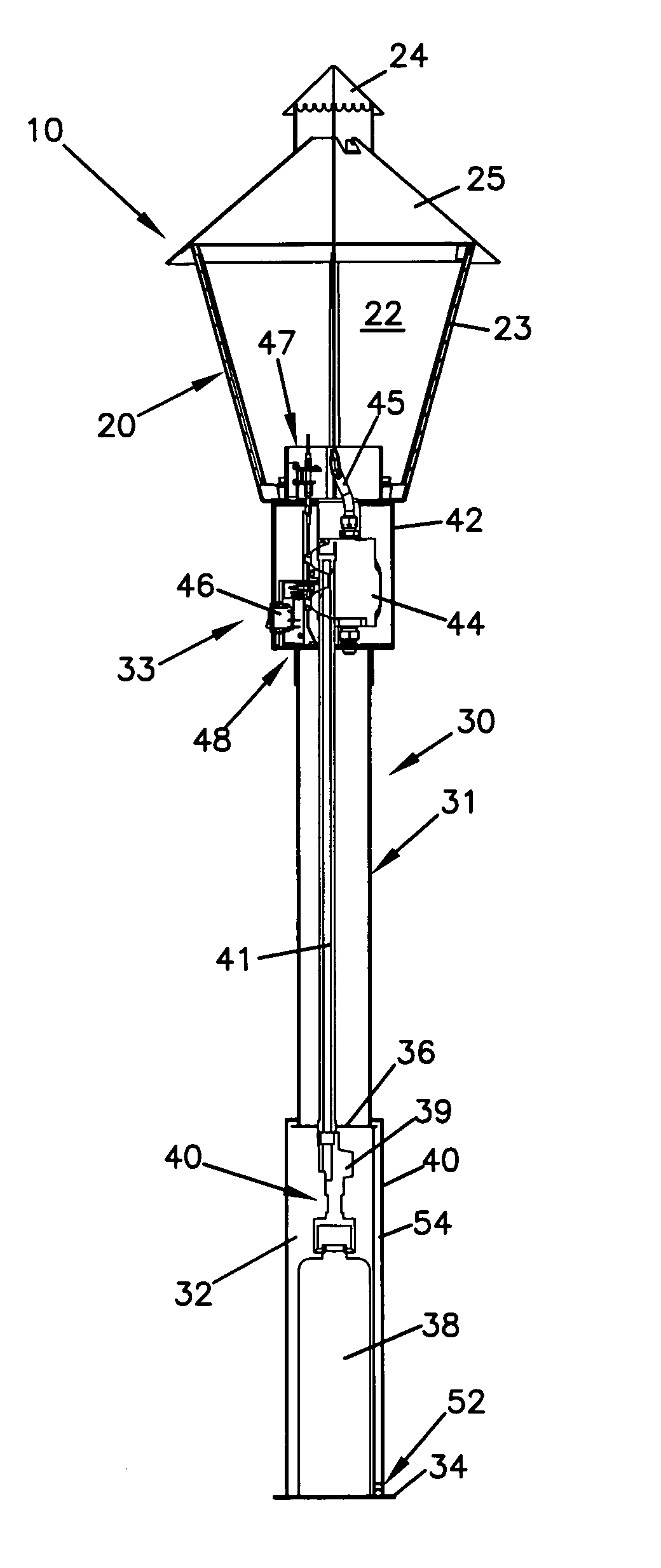
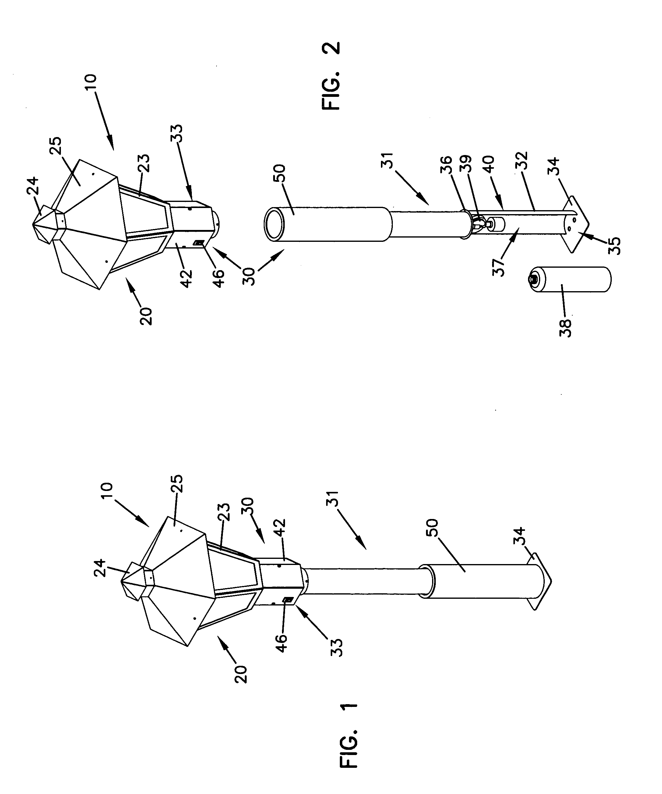
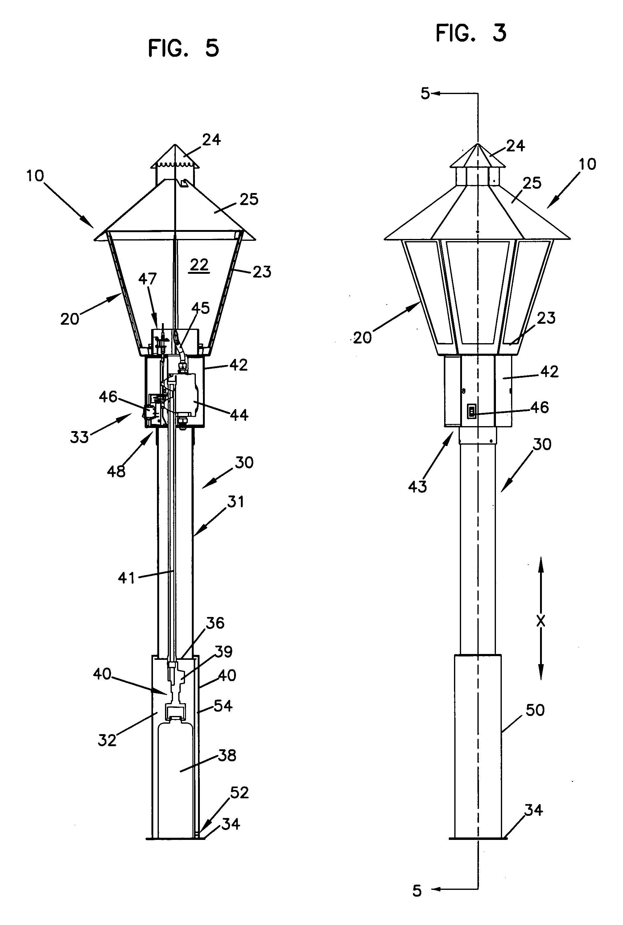
[0014]The present invention generally relates to gas lighting systems and methods of operating gas lighting systems. More specifically, the present invention relates to a gas light that includes a stand member including a recessed portion sized to receive a fuel container. A panel member is coupled to the stand member and configured to cover at least a portion of the recessed portion when in a closed position to conceal at least a portion of the fuel container.

[0015]Referring to FIGS. 1–5, a gas light system 10 is shown. The gas light system 10 is a portable system that can be positioned as desired.

[0016]The gas light system 10 includes a light-generating member 20. The light-generating member 20 defines an interior space 22 (see FIG. 5) in which combustible gas can be ignited to generate a flame that is visible from and generates light to the outside of the light-generating member 20 through one or more transparent panels (not clearly shown) positioned within a frame 23. Alternativ...


PUM


Abstract

A gas light assembly including a stand member having a recessed portion sized to receive a fuel container. The recessed portion is accessible through an opening of the stand member. A panel member is coupled to the stand member and movable between a closed position covering the recessed portion and an open position wherein the recessed portion is accessible for inserting or removing the fuel container.

Description

BACKGROUND OF THE INVENTION[0001]1. Field of the Invention[0002]The present invention generally relates to lighting systems, and more specifically relates to gas light systems and methods of operating the same.[0003]2. Related Art[0004]Outdoor lighting systems typically require a source of energy such as electricity or some type of combustible fuel such as natural gas or propane in order to produce light. Such energy sources are often routed from a home or other living structure as electrical lines or fuel lines that are buried or otherwise concealed in the path between the living structure and the light-generating device. Installing and maintaining such routed lines can be costly and difficult depending on a number of variables including, for example, the distance and terrain separating the living structure and the light-generating device. These lighting systems, in particular gas lighting systems, are also not typically portable between a number of locations. An improved light sys...

Claims


Application Information

Patent Timeline
Patent Type & Authority Patents(United States)
IPC IPC(8): F23D14/28F21S13/12F21S15/00F21V15/01F21V37/00F24C3/00
CPCF21S13/12F23D14/28F21V15/01
Inventor BACHINSKI, THOMAS J.BENNETT, ROBB EDWARDHOLM, DOUGLAS MARK
Owner HON TECH INC
Why Eureka
Try Eureka