Attachable/detachable probing tip system for a measurement probing system

a technology of probing tip and probe, which is applied in the direction of coupling device connection, cathode-ray oscilloscope, instruments, etc., can solve the problems of requiring replacement of the probing tip, loss of use of the probe during the repair period, and the cost of repair, and the design of very wide bandwidth measurement probes with bandwidths of 5 ghz and greater

Active Publication Date: 2006-06-06
TEKTRONIX INC
View PDF4 Cites 43 Cited by
  • Summary
  • Abstract
  • Description
  • Claims
  • Application Information

AI Technical Summary

Problems solved by technology

Excessive force applied to the measurement probe can break the probing tip requiring replacement.
This results in the loss of use of the probe during the repair period and the expense of the repair.
A major difficulty in designing very wide bandwidth measurement probes having bandwidths of 5 GHz and greater is the effects of capacitance and inductance of the probing tip or tips.
A drawback to this design is that each probing tip unit needs to be soldered to one of the probe connection points.
In addition, continued soldering and de-soldering of the probing tip units to the probe connection points run the risk of damaging the probing contact point resulting in the loss of the probe tip unit.
This may require a user to populate the device under test with multiple probe tip units which drives up the probing solution cost.

Method used


Image

  • Attachable/detachable probing tip system for a measurement probing system
  • Attachable/detachable probing tip system for a measurement probing system
  • Attachable/detachable probing tip system for a measurement probing system

Examples


Embodiment Construction

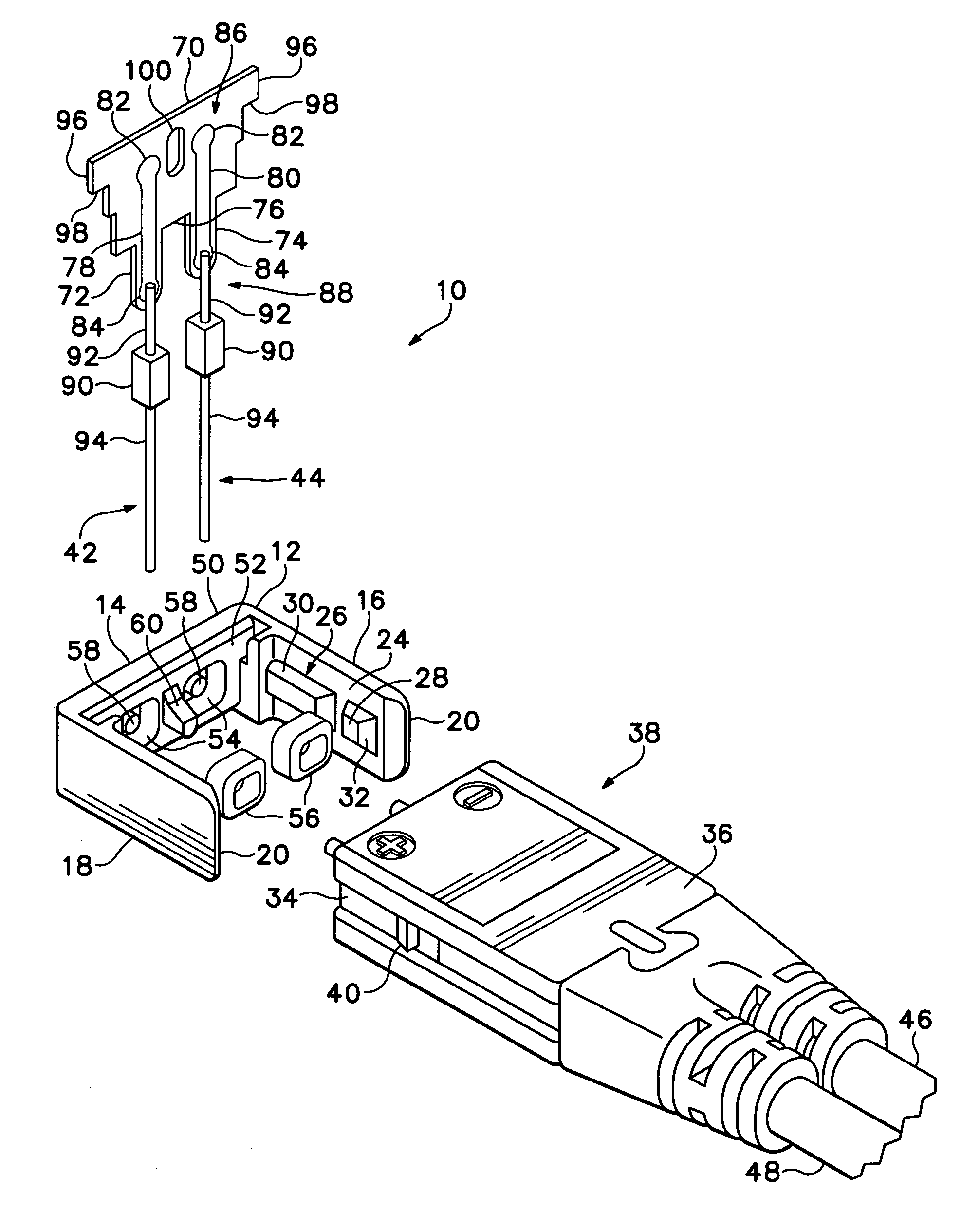
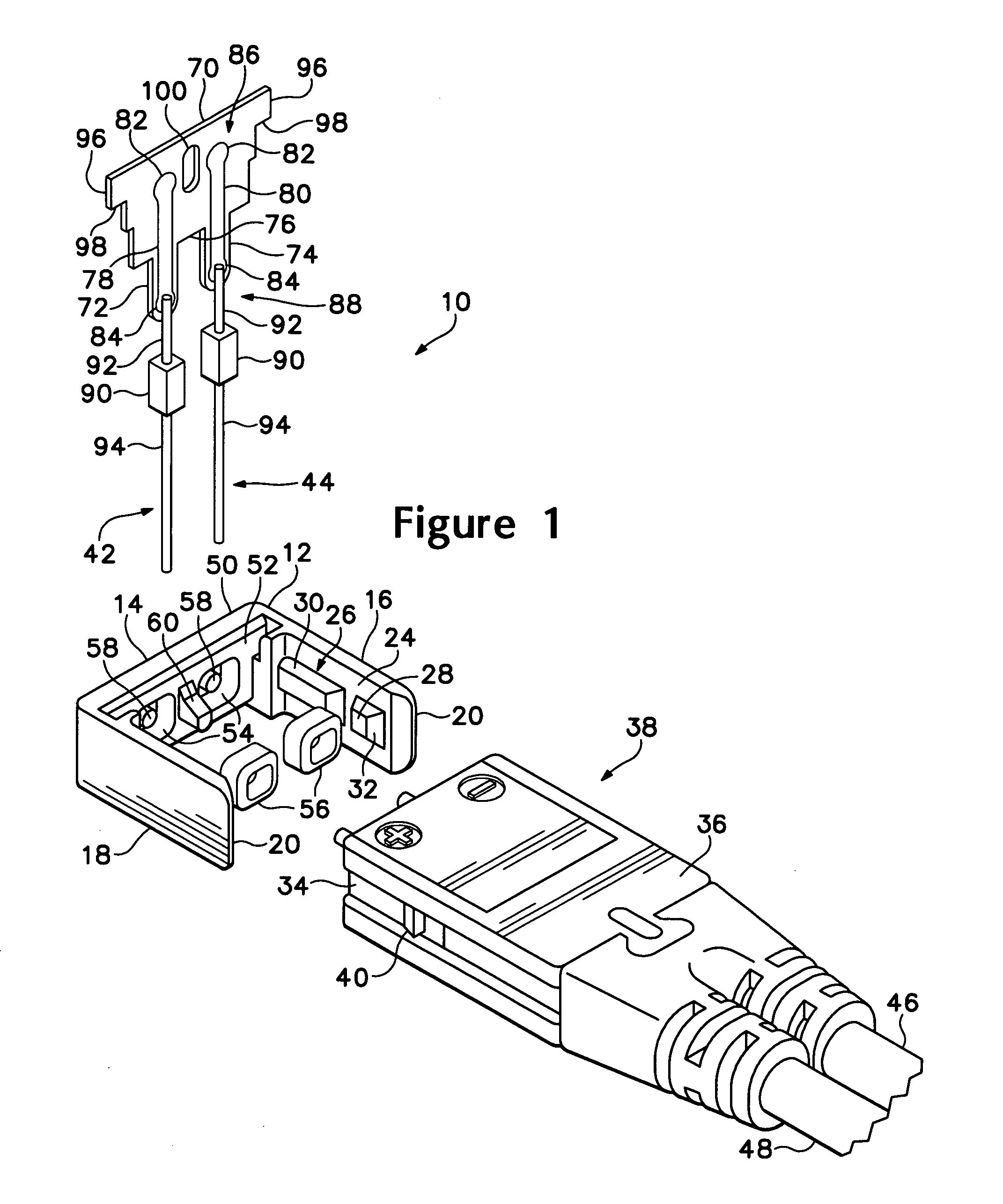
[0020]FIG. 1 is an exploded perspective view illustrating a first embodiment of the attachable / detachable probing tip system 10 of the present invention. The probing tip system 10 has a housing 12 having a probing tip mounting member 14 and substantially orthogonal attachment arms 16, 18 extending from the probing tip mounting member 14, as best seen in FIG. 2. The housing 12 is preferably formed a non-conductive, injection moldable material, such as ABS plastic, poly-carbonate, ABS-poly-carbonate blend, or the like. The distal ends of the attachment arms 16, 18 are formed with inwardly disposed bevels 20. The inner surface 24 of each of the attachment arms 16, 18 has a segmented rib 26 with each segment 28, 30 having a beveled rearward face 32. The segmented ribs 26 engage channels 34 on either side of a housing 36 of a probing tip member 38. Each channel 34 has a boss 40 formed in the channel that is captured between the segments 28, 30 of the segmented ribs 26 to secure the probi...


PUM


Abstract

A attachable / detachable probing tip system (10) has a housing (12) that includes a probing tip mounting member (14) and opposing substantially orthogonal attachment (16, 18) arms extending from the probing tip mounting member. The attachment arms define an inner surface of the probing tip mounting member in which is disposed at least a first a non-compressive set, resilient member (56). First and second probing tips (42, 44) are disposed over the non-compressive, resilient member (56) and secured to the housing by latching means (60, 66, 92, 96, 100, 130). The attachable / detachable probing tip system allows mounting of the probing tips (42, 44) to probing contacts on a device under test without a probe body or probing tip member (38) being attached. The attachment arms (16, 18) allows a probe body or probing tip member (38) to be attached and detached to the probing tip system (10). The probing tip member (38) includes contact pins that engage contact areas (82, 82, 92) of the probing tips (42, 44).

Description

BACKGROUND OF THE INVENTION[0001]The present invention generally relates to probing tips for measurement probes and more particularly to an attachable / detachable probing tip system for a measurement probing system where the probing tips of the probing tip system are mountable on a device under test separate from other components of the measurement probing system.[0002]Voltage measurement probes acquire electrical signals from a device under test and couple the acquired signal to a measurement instrument, such as an oscilloscope or the like, via an electrical cable. A typical voltage probe has a probe head with an electrically conductive hollow tube having a substrate disposed therein. The substrate has passive or active circuitry for conditioning the acquired signal prior to being coupled to the measurement instrument. The end of the hollow tube has an insulating plug disposed therein with a coaxially disposed probing tip extending out of the plug in both directions. The portion of ...

Claims


Application Information

Patent Timeline
Patent Type & Authority Patents(United States)
IPC IPC(8): G01R31/02G01R1/073G01R1/067G01R13/20H01R13/502
CPCG01R1/06711G01R1/06788G01R1/06772G01R1/20
Inventor MARTIN, JIM L.GESSFORD, MARC A.POOLEY, WILLIAM R.LAW, WILLIAM Q.POLLOCK, IRA G.HAGERUP, WILLIAM A.
Owner TEKTRONIX INC
Why Eureka
Try Eureka