Multi-terminal connector strip and procedure for the sealing thereof

a multi-terminal connector and connector strip technology, applied in the direction of coupling device details, coupling device connections, contact members penetrating/cutting insulation/cable strands, etc., can solve the problems of not being able to achieve effective solutions, space open to the air and consequently subject to the above oxidation,

Inactive Publication Date: 2006-06-06
COMMSCOPE CONNECTIVITY SPAIN
View PDF8 Cites 16 Cited by
  • Summary
  • Abstract
  • Description
  • Claims
  • Application Information

AI Technical Summary

Benefits of technology

[0012]The intermediate transversal partitions situated between the terminals that form a pair, are of less height that the main partitions in order to be able to augment the volume of sealant, and simultaneously increase the effectiveness of the sealing that it provides while managing to lose the least amount possible of sealant during the sealing operation and subsequent connection of the conductors.
[0016]Clearly the sealing procedure consists in pouring over the chamber or housing of the terminals, a quantity of suitable sealing gel or fluid until a level is reached that is located above the upper level of the terminals and below the upper level of the side edges of the actual strip, all of this in order to achieve that both the terminals and the zone of contact between the terminal and the conductor wires are completely immersed in the gel, so that once dried or cured it is possible to proceed to the location and subsequent connection of the conductor wires with the collaboration of the tool, without risk of loss or extension of the sealing product itself.
[0017]To achieve this, the sealing gel or product which is employed, once it has dried or cured, acquires a gelatinous or semi-solid state with a certain degree of elasticity, in such a way that it permits insertion therein of the tool together with the conductor wire, and also when the wire has been connected and the tool removed, said elastic property of the gelatinous mass causes the gel to recover its initial volume (prior to the insertion of the tool), and closes the space which the tool originated on its insertion, whereby the chamber is perfectly flooded with sealing gel or product which guarantees the seal.

Problems solved by technology

Notwithstanding, though this connection system proves effective, it has a drawback, and this is that the chambers or housings for the respective terminals are open to the air, it being possible for dampness to enter on the pertinent conductor which could give rise to a subsequent process oxidation, which can be worsened due to the frequency at which the signal is transmitted, since higher signal frequencies produce increased oxidation.
In other cases, in order to prevent oxidation, grease is employed as a sealing agent, which, by its very nature does not require curing, but which even so is lost on connecting the wires, and also the actual tool which acts on the terminals, strips away part of the grease when the operation is performed, leaving spaces open to the air and consequently subject to the aforementioned oxidation.
Thus, in order for the fluid in question not to be displaced and lost while drying, the strip is inserted into a mould covering the slots existing, which clearly does not signify an effective solution.
The drawback that this last system has, is that the gums are of a limited duration, that is, very short, around a couple of days, meaning that they have to be changed continuously.

Method used


Image

  • Multi-terminal connector strip and procedure for the sealing thereof
  • Multi-terminal connector strip and procedure for the sealing thereof
  • Multi-terminal connector strip and procedure for the sealing thereof

Examples


Embodiment Construction

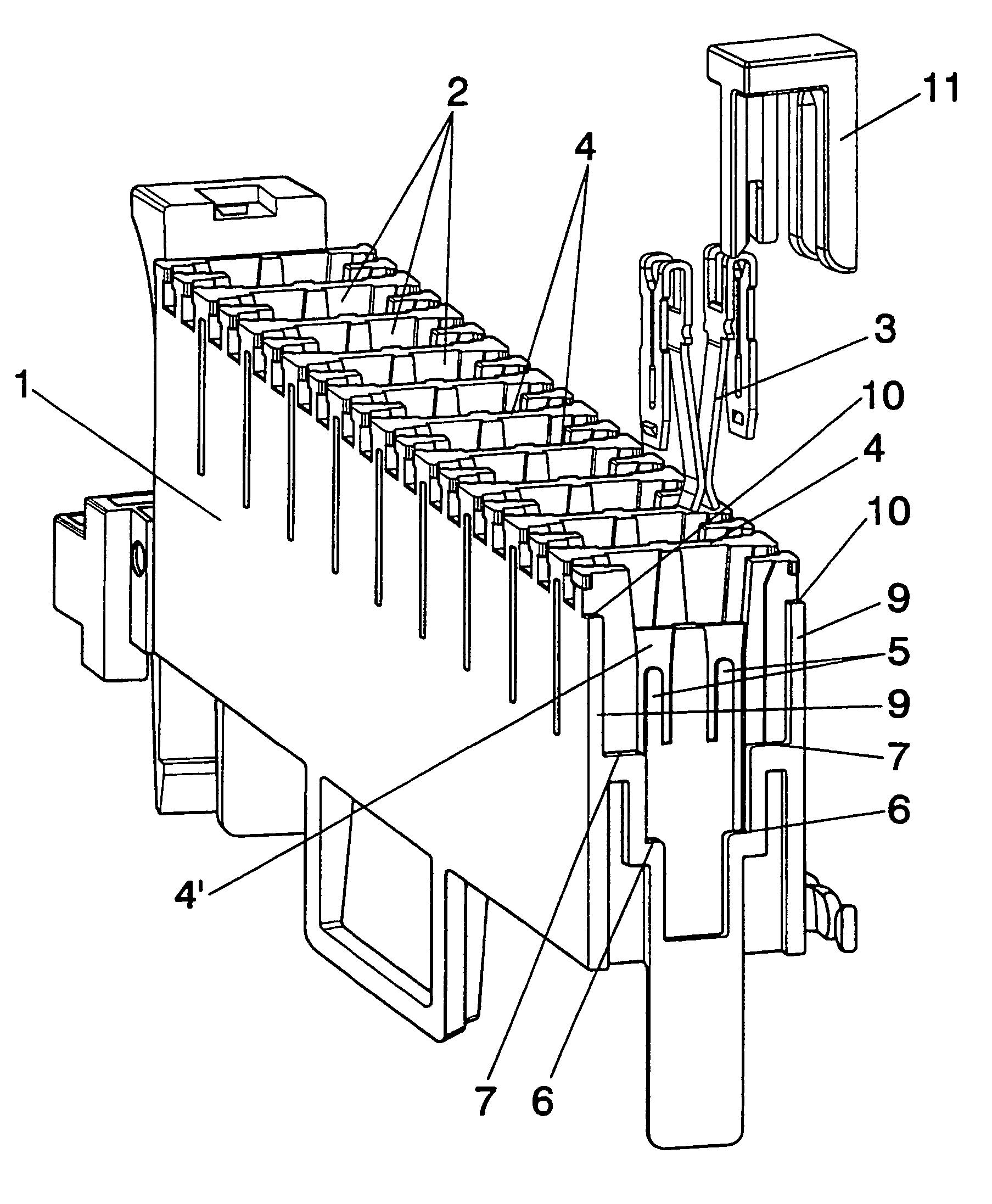
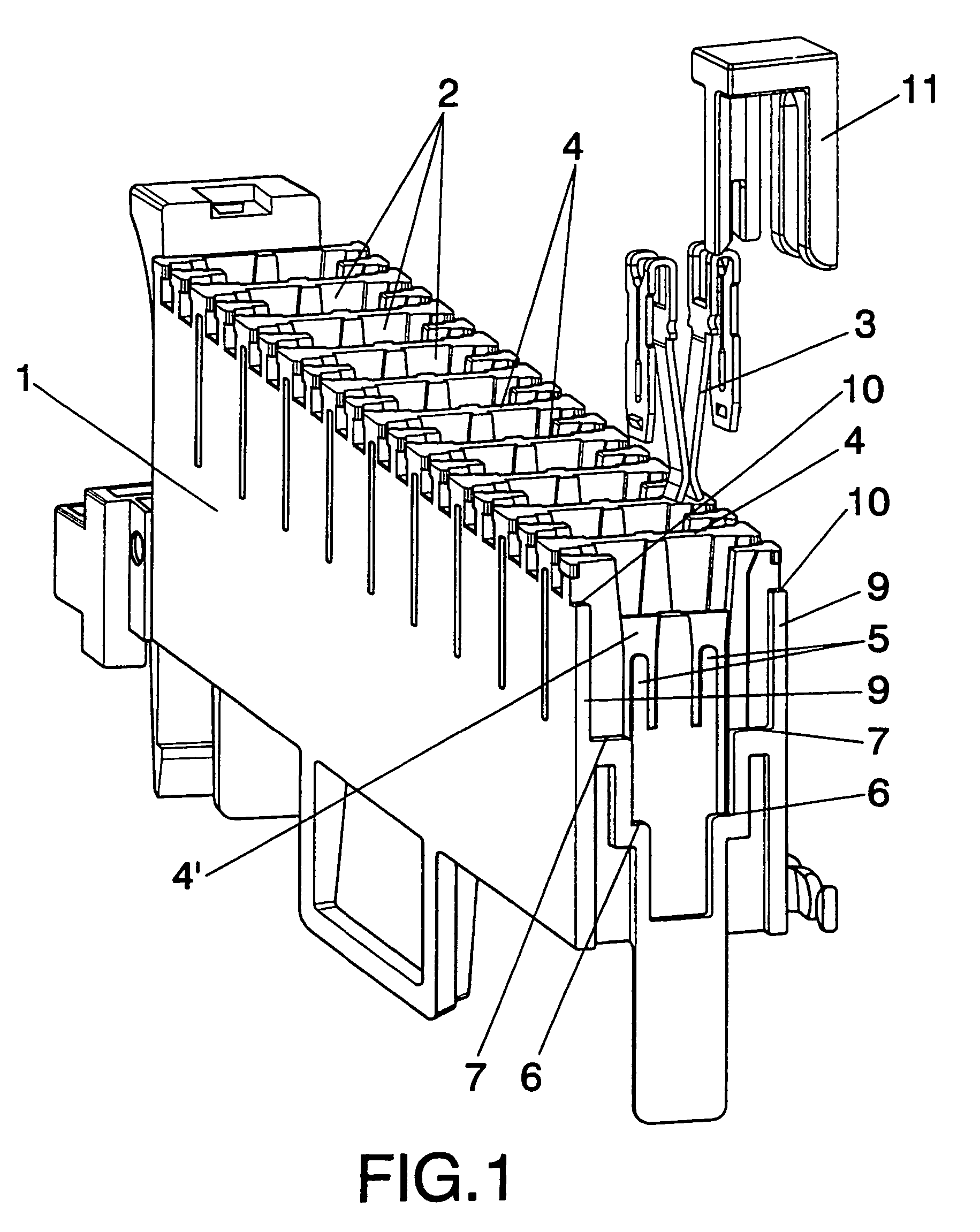
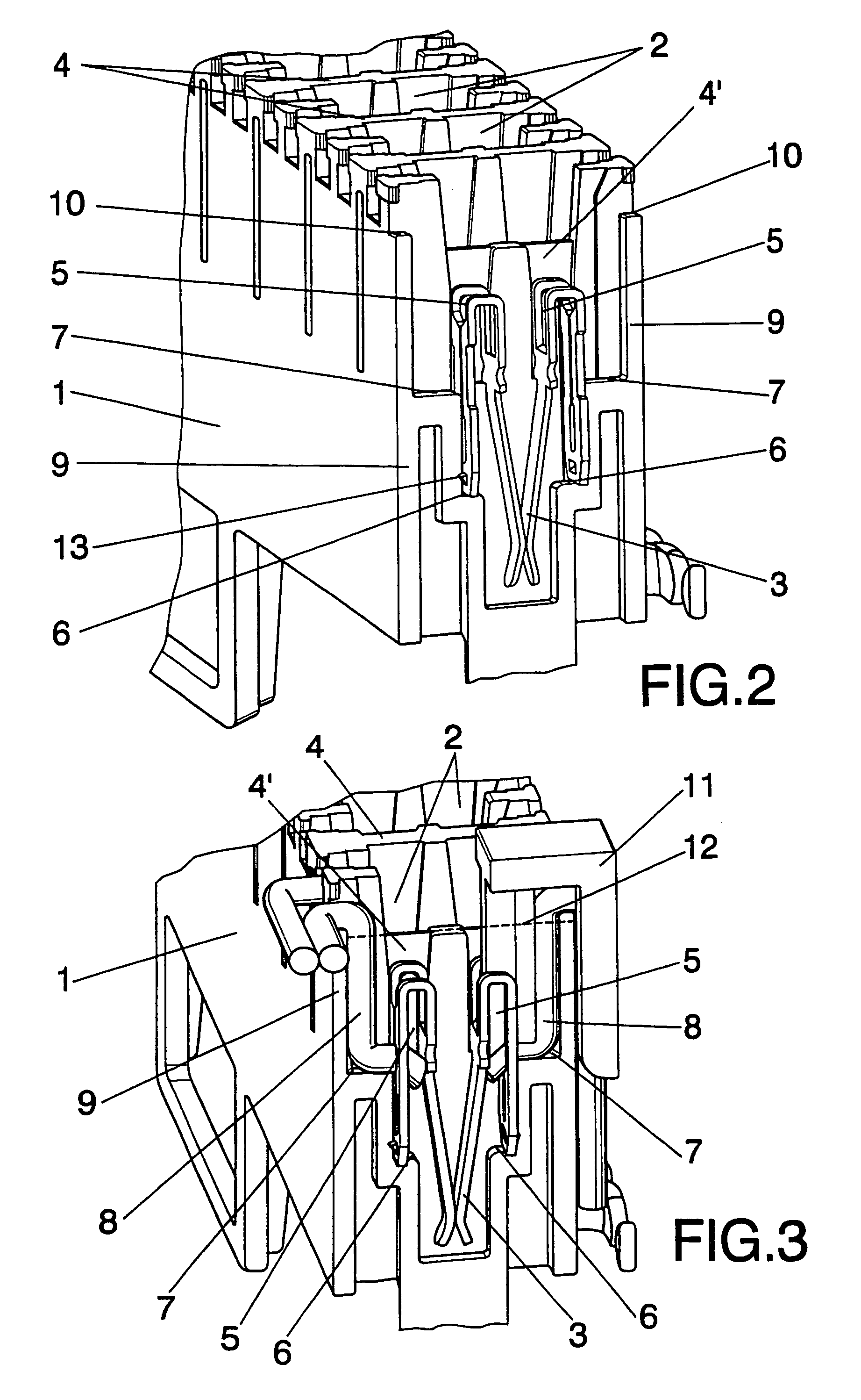
[0023]As can be seen from the figures referenced, the strip (1) of the invention, constituted by an elongated body in which are formed the pertinent housings or chambers (2) for each pair of terminals (3), has the particularity that each one of its housings or chambers (2) is made separate and independent of the rest by means of respective transversal partitions (4).

[0024]Moreover, between each of the terminals (3) which forms a pair, there are other transversal and intermediate partitions (4′) of less height with the object of occupying the least possible volume within the chamber (2) and so permit the pouring in of a greater quantity of sealing product with the object of enhancing its effectiveness and minimising the loss of sealing product during the sealing operation that shall be explained later. Specifically the level of the intermediate partitions (4′) is situated close to and above the highest level of the terminals (3), just as is shown in FIG. 2.

[0025]Internally these hous...


PUM


Abstract

A strip is provided with a series of housings for a like number of terminals to which conductor wires accede thrust by a tool in order to establish a connection, by means of displacing the conductor wires over the terminals. Each housing or chamber is independent of those adjacent, the separation being constituted by means of transversal partitions, which makes possible the pouring of a sealing gel into the respective housing chamber up to a level which is at a height lower than the entrance step of the conductor wires and above the edge of the terminals, with the objective that both said terminals and the connections thereof with the conductors be immersed in the sealing gel in order to prevent oxidation on the connections.

Description

RELATED APPLICATIONS[0001]The present application is a National Phase application of PCT / GB02 / 04810 filed on Oct. 24, 2002 and published in English, which claims priority from Application ES 200102520 filed on Nov. 14, 2001.BACKGROUND OF THE INVENTION[0002]The innovation of the strip consists in the internal configuration of the terminal housing chambers, and also in that said chambers are made independent by means of transversal partitions.[0003]A further object of the invention is a procedure for sealing the strip, said sealing being performed by pouring suitable gel or fluid up to a determined height in each of the chambers in which the terminal is located, so that when it has cured, the conductor wires are housed and duly connected.[0004]Multi-terminal connection strips are known that employ pairs of terminals fixed to each other in an elongated row for their connection, and the terminals of which are capable of displacing the insulation of the conductors which are inserted by p...

Claims


Application Information

Patent Timeline
Patent Type & Authority Patents(United States)
IPC IPC(8): H01R4/24H01R9/22H01R13/52
CPCH01R13/5216H01R4/2429H01R13/52
Inventor ARIAS, JUAN TOMASGIMENO, JOSE VICENTE
Owner COMMSCOPE CONNECTIVITY SPAIN
Why Eureka
Try Eureka