Liposuction apparatus with pressurized liquid spray and liposuction method using the apparatus

a technology of liposuction apparatus and pressurized liquid, which is applied in the direction of fluid jet surgical cutters, infusion syringes, therapy, etc., can solve the problems of inability to perform multiple operations in one day, requires considerable physical effort on the part of the surgeon to move the cannula back and forth, and achieves less blood loss.

Inactive Publication Date: 2006-06-06
ESCHMANN HLDG LTD
View PDF38 Cites 27 Cited by
  • Summary
  • Abstract
  • Description
  • Claims
  • Application Information

AI Technical Summary

Benefits of technology

[0049]Among the numerous advantages of the invention, it should be mentioned that there is not only less blood loss during the procedure, but recuperation and post-operative care are significantly improved.

Problems solved by technology

While this technique is generally satisfactory because of its simplicity and effectiveness, it requires considerable physical effort on the part of the surgeon to move the cannula back and forth.
The intervention is very physically taxing for the surgeon who, despite the high demand, cannot perform multiple operations in one day.
Furthermore, during the procedure the surgeon may become so tired from the effort expended that he moves in a random, uncontrolled or even rough fashion, so the fat is not removed homogeneously.
This causes the appearance of esthetically objectionable “waves” or rolls of fat at the surface of the treated area.
In addition, another difficulty encountered during a liposuction intervention is that the fat cells are sometimes difficult to detach from surrounding tissue, often forming clumps or nodules that block the cannula.
In this case the cannula must be removed, unblocked and reintroduced, thereby prolonging the intervention needlessly and causing additional trauma.
However, this requires very strong pressure, which can coincidentally harm surrounding tissue.
Obviously, this inflicts more trauma on the patient due to introduction of a larger cannula and causes significant scarring, requiring more time for reabsorption.
The result is an intervention that is challenging for the surgeon, needlessly long and often painful for the patient, in which it is impossible to completely control fatty tissue extraction, often resulting in an irregular, unesthetic epidermal surface over the treated area.

Method used


Image

  • Liposuction apparatus with pressurized liquid spray and liposuction method using the apparatus
  • Liposuction apparatus with pressurized liquid spray and liposuction method using the apparatus
  • Liposuction apparatus with pressurized liquid spray and liposuction method using the apparatus

Examples


Embodiment Construction

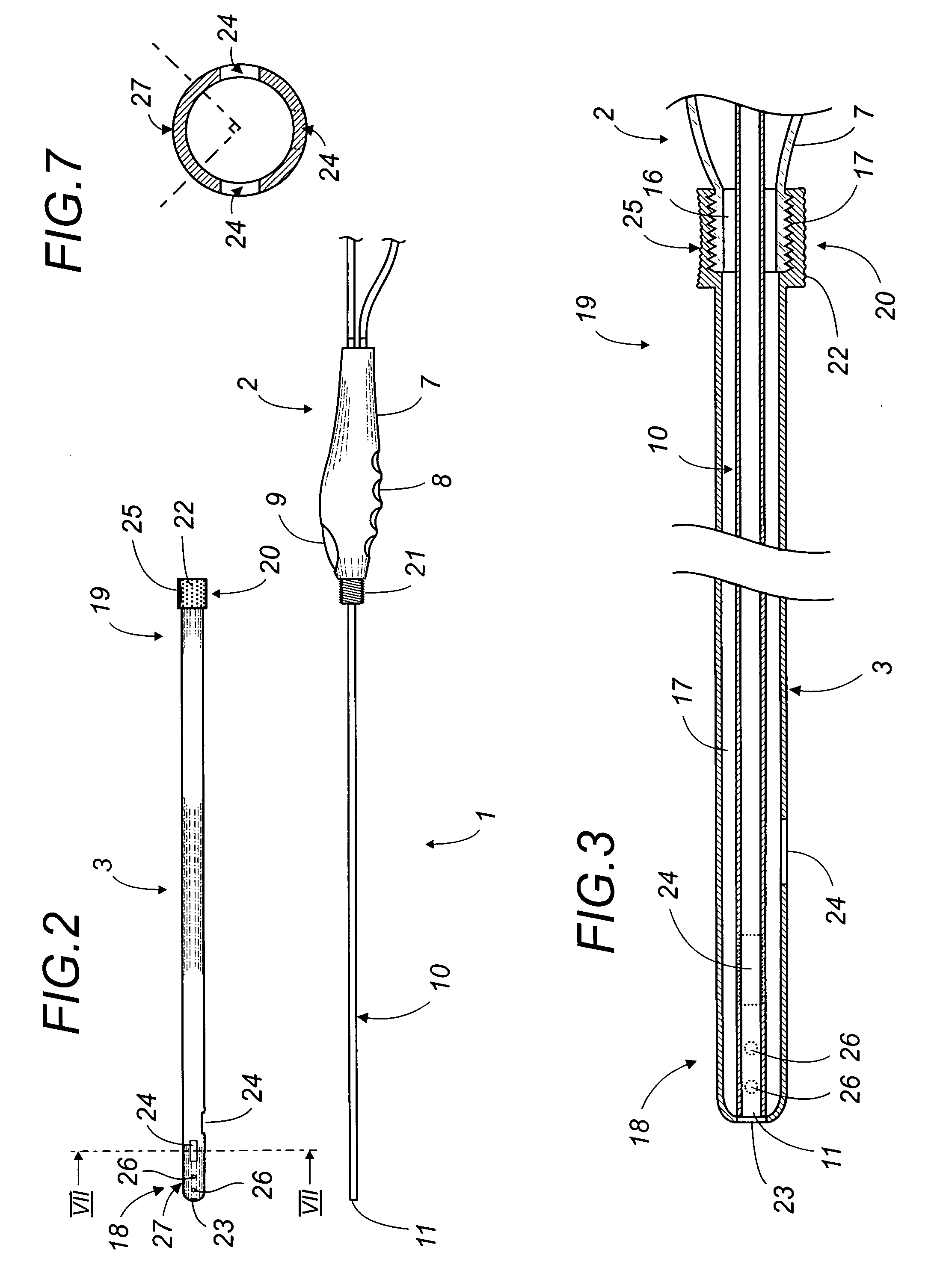
[0058]The liposuction apparatus according to the present invention will now be described in detail with reference to FIGS. 1 through 6. Equivalent elements shown in the different drawings will bear the same reference numerals.

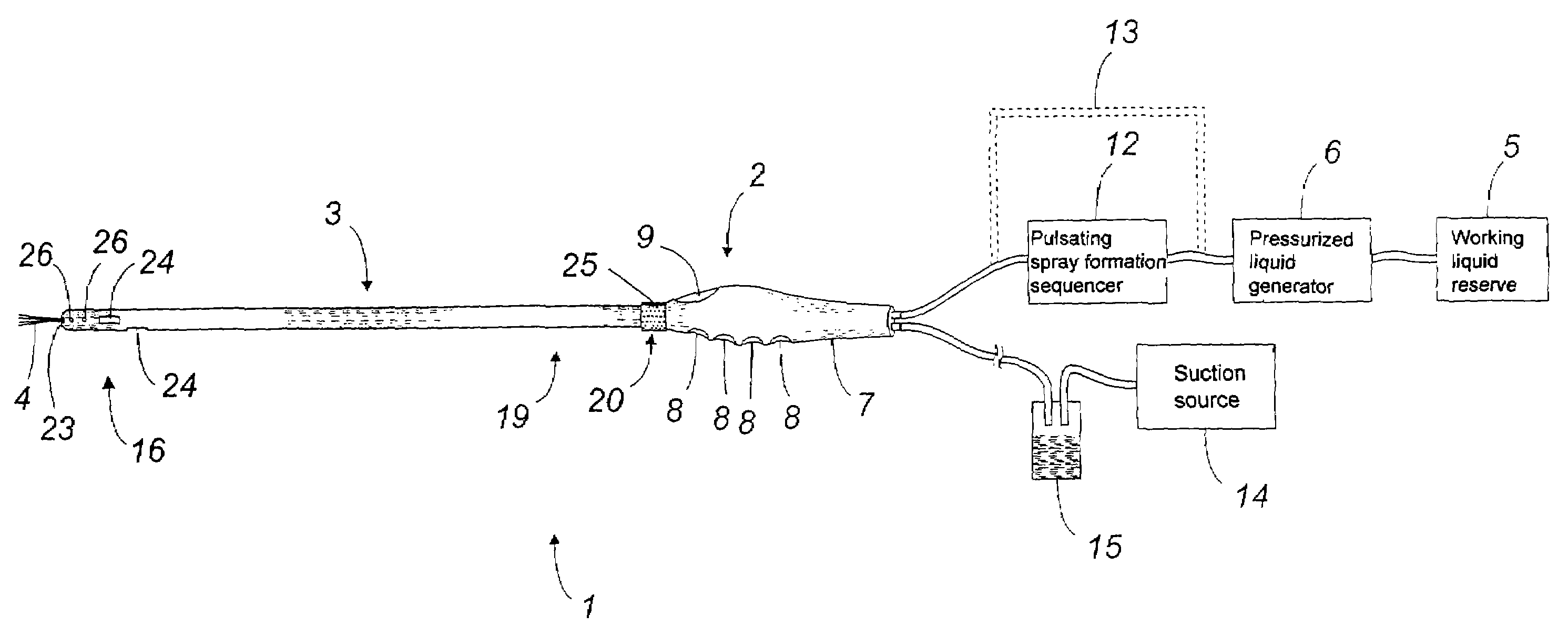
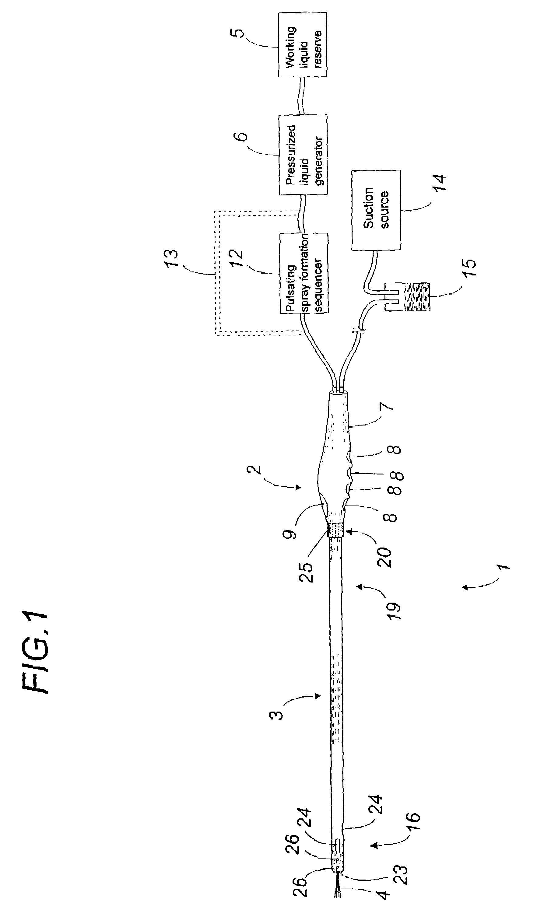
[0059]The liposuction apparatus 1 according to the invention comprises a hand piece 2 to which a liposuction cannula 3 may be attached.

[0060]Liposuction apparatus 1 allows one or more sprays 4 of sterile pressurized liquid to be aimed at the fatty tissue in order to disaggregate and emulsify the fatty tissue, allowing the fatty tissue to be suctioned far more easily.

[0061]For this purpose hand piece 2 is connected to a sterile reserve 5 of sterile working liquid which may be pressurized by a pressurized liquid generator 6.

[0062]The reserve is a disposable sterile container of sterile working liquid.

[0063]This reserve may consist, for example, of a flexible plastic pouch containing the sterile working liquid, enclosed in a sterile area that is pressurized by fil...


PUM


Abstract

The liposuction apparatus (1) comprises in combination a tubular canula (3) having at its distal extremity (18) one or more suction orifices (24) and connected at its proximate extremity (19) to a suction source (14) in communication with these orifices, and a hand piece (2) delivering a spray of working liquid (4) under pressure. The hand piece delivers the spray of liquid under pressure using a conduit opening into an ejection orifice which, when the canula is attached to the hand piece, is located opposite an ejection orifice in the canula located at its distal extremity. A liposuction method using the apparatus is also taught. This invention is of interest to manufacturers and users of surgical equipment.

Description

FIELD OF THE INVENTION[0001]The present invention concerns a liposuction apparatus with a pressurized liquid spray as well as a liposuction method using the apparatus.BACKGROUND OF THE INVENTION[0002]Liposuction or lipoaspiration is a cosmetic surgery technique that has been in use for about twenty years and which is rapidly becoming the most widely practiced cosmetic surgery procedure in the world.[0003]It consists of using suction to eliminate localized deposits of excessive subcutaneous fat in certain areas of the body, for example, the chest, the buttocks, the hips, or the thighs.[0004]The conventional apparatus for this type of intervention comprises a hollow cylindrical cannula with one or more orifices near its distal extremity. This cannula is connected at the other end to a suction source, generally a vacuum pump, for the purpose of suctioning fat cells through the orifices and then evacuating them through the hollow interior portion of the cannula. A receptacle for recover...

Claims


Application Information

Patent Timeline
Patent Type & Authority Patents(United States)
IPC IPC(8): A61M1/00A61B17/22
CPCA61B17/32037A61M1/0064A61M1/0058A61M2202/08A61M1/774A61M1/89
Inventor GONON, BERTRANDGARRIDO, IGNACIO
Owner ESCHMANN HLDG LTD
Why Eureka
Try Eureka