Fractile antenna arrays and methods for producing a fractile antenna array

a technology of antenna arrays and antenna arrays, applied in the field of fractile antenna arrays, can solve the problems of arrays with non-uniform spacing of array elements, process is not simple, etc., and achieve the effect of improving broadband performan

Inactive Publication Date: 2006-06-06
PENN STATE RES FOUND
View PDF3 Cites 10 Cited by
  • Summary
  • Abstract
  • Description
  • Claims
  • Application Information

AI Technical Summary

Benefits of technology

[0007]The present invention is also directed to a method for generating an antenna array having improved broadband performance. A plane is tiled with a plurality of non-uniform shaped unit cells of an antenna array. The non-uniform shape of the unit cells and the tiling of said unit cells are then optimized.
[0008]The present invention is also directed to a method for rapidly forming a radiation pattern of a fractile array. A pattern multiplication for fractile arrays is employed wherein a product formulation is derived for the radiation pattern of a fractile array for a desired stage of growth. The pattern multiplication for the fractile ar

Problems solved by technology

However, one of the main drawbacks in these cases is that the design process is not based on simple deterministic design rules and leads to arrays with non-uniformly spaced elements.

Method used


Image

  • Fractile antenna arrays and methods for producing a fractile antenna array
  • Fractile antenna arrays and methods for producing a fractile antenna array
  • Fractile antenna arrays and methods for producing a fractile antenna array

Examples


Embodiment Construction

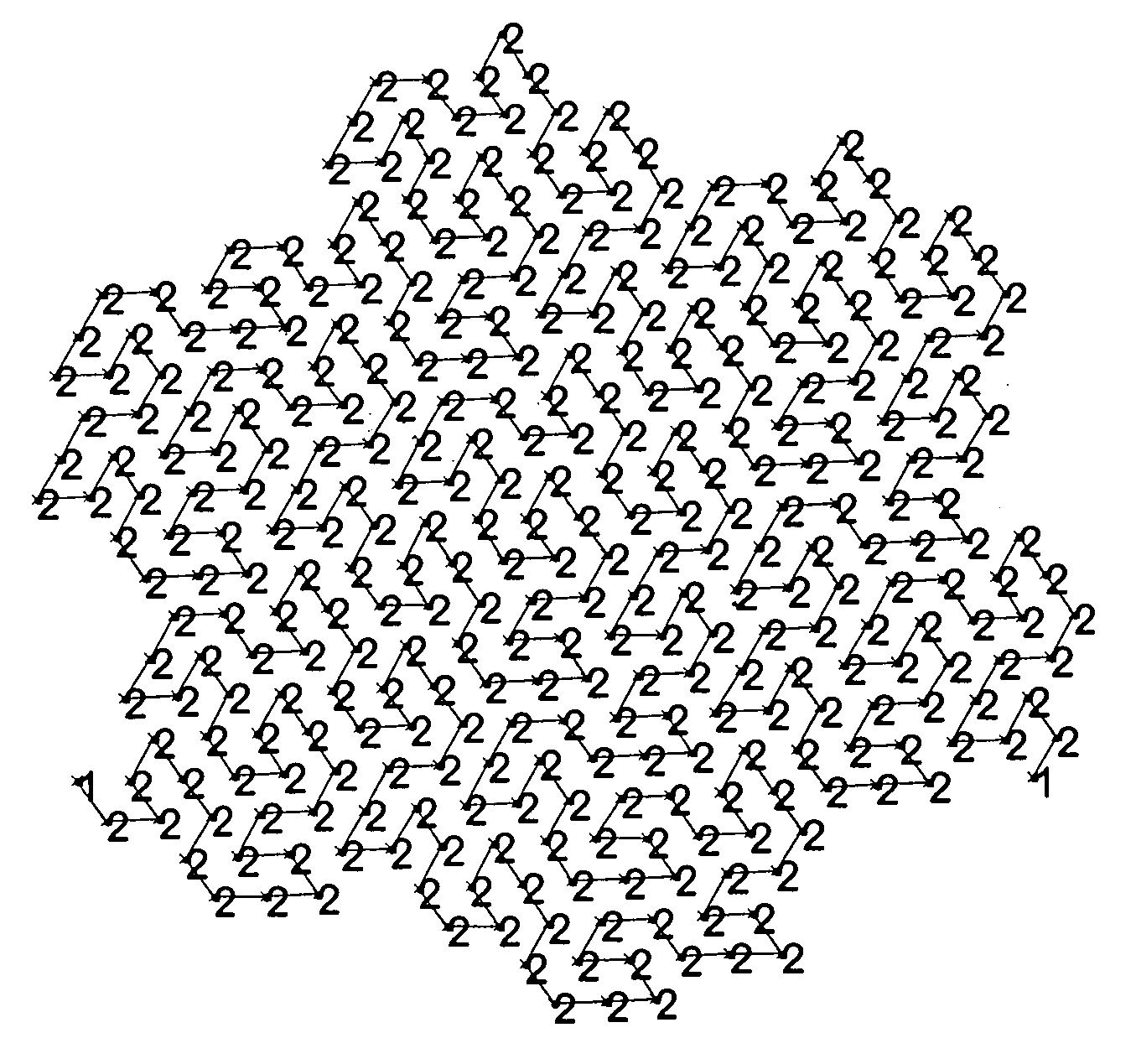
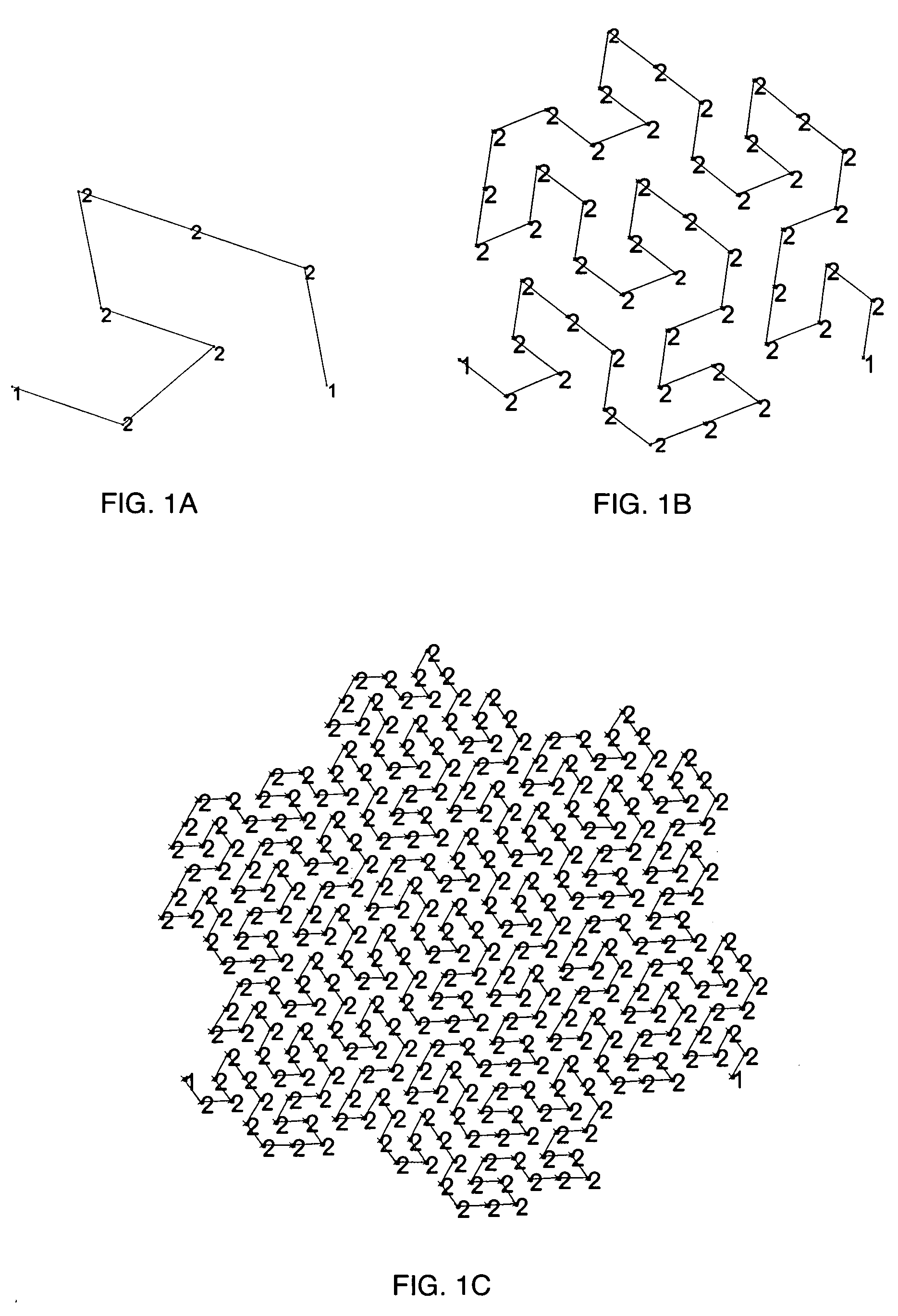
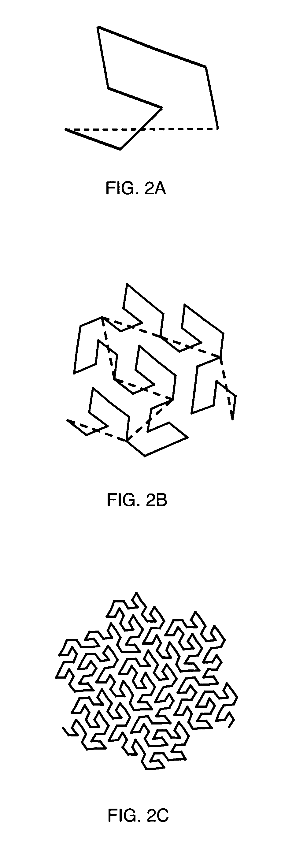
[0027]FIGS. 1A–1C illustrate the antenna element locations and associated current amplitude excitations for a stage 1, stage 2 and stage 3 Peano-Gosper fracticle arrays where the antenna elements are distributed over a planar area (e.g., in free-space, over a geographical area, mounted on an Electromagnetic Band Gap (EBG) surface or an Artificial Magnetic Conducting (AMC) ground plane, mounted on an aircraft, mounted on a ship, mounted on a vehicle, etc.) A fractile array is defined as an array with a fractal boundary contour that tiles the plane without leaving any gaps or without overlapping, wherein the fractile array illustrates improved broadband characteristics. The numbers 1 and 2 denote each antenna element's relative current amplitude excitation. The minimum spacing between antenna elements is assumed to be held fixed at a value of dmin for each stage of growth. The antenna elements may be comprised of shapes and sizes of elements well know to those skilled in the art. Some...


PUM


Abstract

An antenna array comprised of a fractile array having a plurality of antenna elements uniformly distributed along a Peano-Gosper curve. An antenna array comprised of an array having an irregular boundary contour comprising a plane tiled by a plurality of fractiles covering the plane without any gaps or overlaps. A method for generating an antenna array having improved broadband performance wherein a plane is tiled with a plurality of non-uniform shaped unit cells or an antenna array, the non-uniform shaped and tiling of the unit cells are then optimized. A method for rapidly forming a radiation pattern of a fractile array employing a pattern multiplication for fractile arrays wherein a product formulation is derived for the radiation pattern of a fractile array for a desired stage of growth. The pattern multiplication is recursively applied to construct higher order fractile array forming an antenna array.

Description

[0001]This application claims the benefit of Provisional Application No. 60 / 398,301, filed Jul. 23, 2002.FIELD OF THE INVENTION[0002]The present invention is directed to fractile antenna arrays and a method of producing a fractile antenna array with improved broadband performance. The present invention is also directed to methods for rapidly forming a radiation pattern of a fractile array.BACKGROUND OF THE INVENTION[0003]Fractal concepts were first introduced for use in antenna array theory by Kim and Jaggard. See, Y. Kim et al., “The Fractal Random Array,” Proc. IEEE, Vol. 74, No. 9, pp. 1278–1280, 1986. A design methodology was developed for quasi-random arrays based on properties of random fractals. In other words, random fractals were used to generate array configurations that are somewhere between completely ordered (i.e., periodic) and completely disordered (i.e., random). The main advantage of this technique is that it yields sparse arrays that possess relatively low sidelobe...

Claims


Application Information

Patent Timeline
IPC IPC(8): H01Q1/38H01Q5/00H01Q21/06
CPCH01Q21/061
Inventor WERNER, DOUGLAS H.KUHIRUN, WAROTHWERNER, PINGJUAN L.
Owner PENN STATE RES FOUND
Why Eureka
Try Eureka