Flexible multichannel WLAN access point architecture

a multi-channel access point and flexible technology, applied in the field of radio communications, can solve the problems of not meeting the needs of multi-channel deployment in very dense user environments such as conference rooms and classrooms, and not being able to adapt to the varying needs of different end-users, and being difficult to anticipate the future standards of multi-channel networking

Inactive Publication Date: 2006-06-06
CISCO TECH INC
View PDF2 Cites 101 Cited by
  • Summary
  • Abstract
  • Description
  • Claims
  • Application Information

AI Technical Summary

Problems solved by technology

It is difficult to anticipate the future standards of multichannel networking, and the specific needs of individual WLAN deployments will inevitably vary in accordance with customer needs.
However, such a deployment would require multiple installations, adequate physical separation, and multiple wires back to the network connection.
Also, such an approach does not address the need for deployment of multiple channels in very dense user environments such as conference rooms and classrooms.
Single, high-throughput APs having three or four 802.11(a) channels are known and have been considered for dense client coverage, but these approaches are fixed in channelization, and are not sufficiently flexible to adapt to the varying needs of different end-users.
Thus, there are no current solutions available that can provide a useful selection of 802.11 band types and the number of channels to be supported within each band.

Method used


Image

  • Flexible multichannel WLAN access point architecture
  • Flexible multichannel WLAN access point architecture
  • Flexible multichannel WLAN access point architecture

Examples


Embodiment Construction

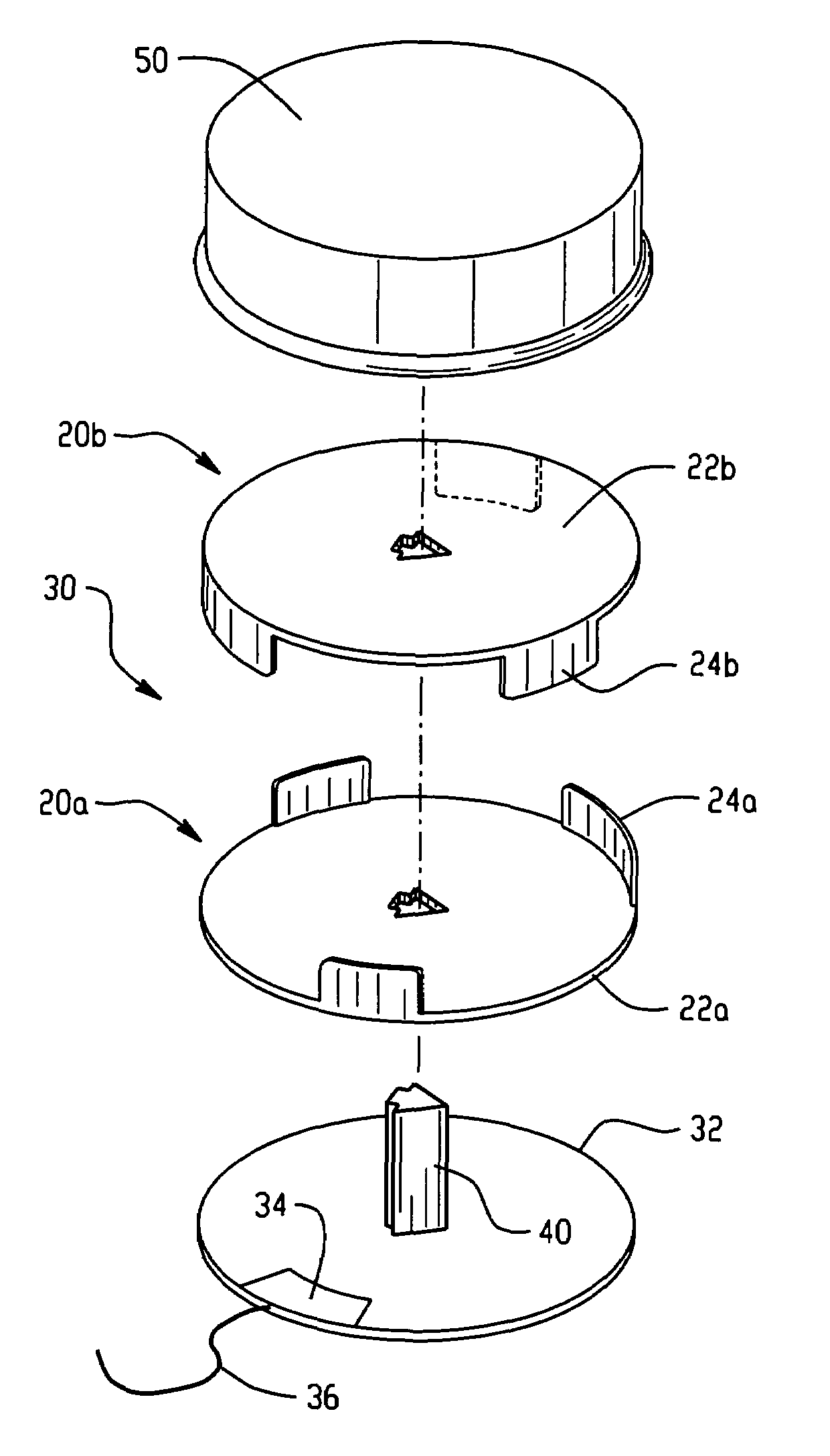
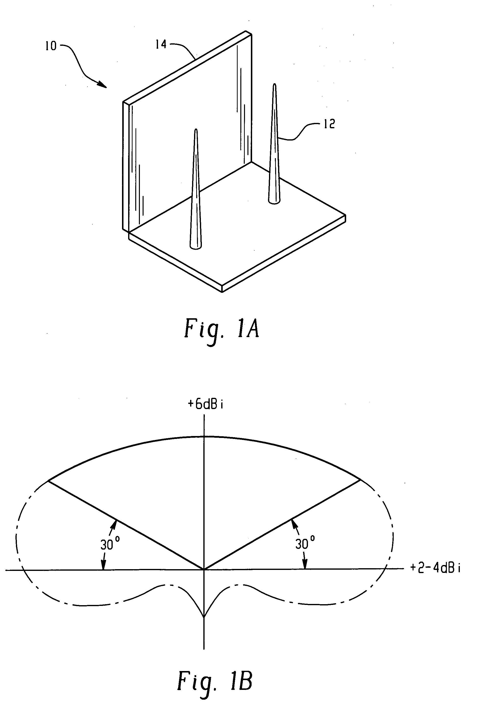
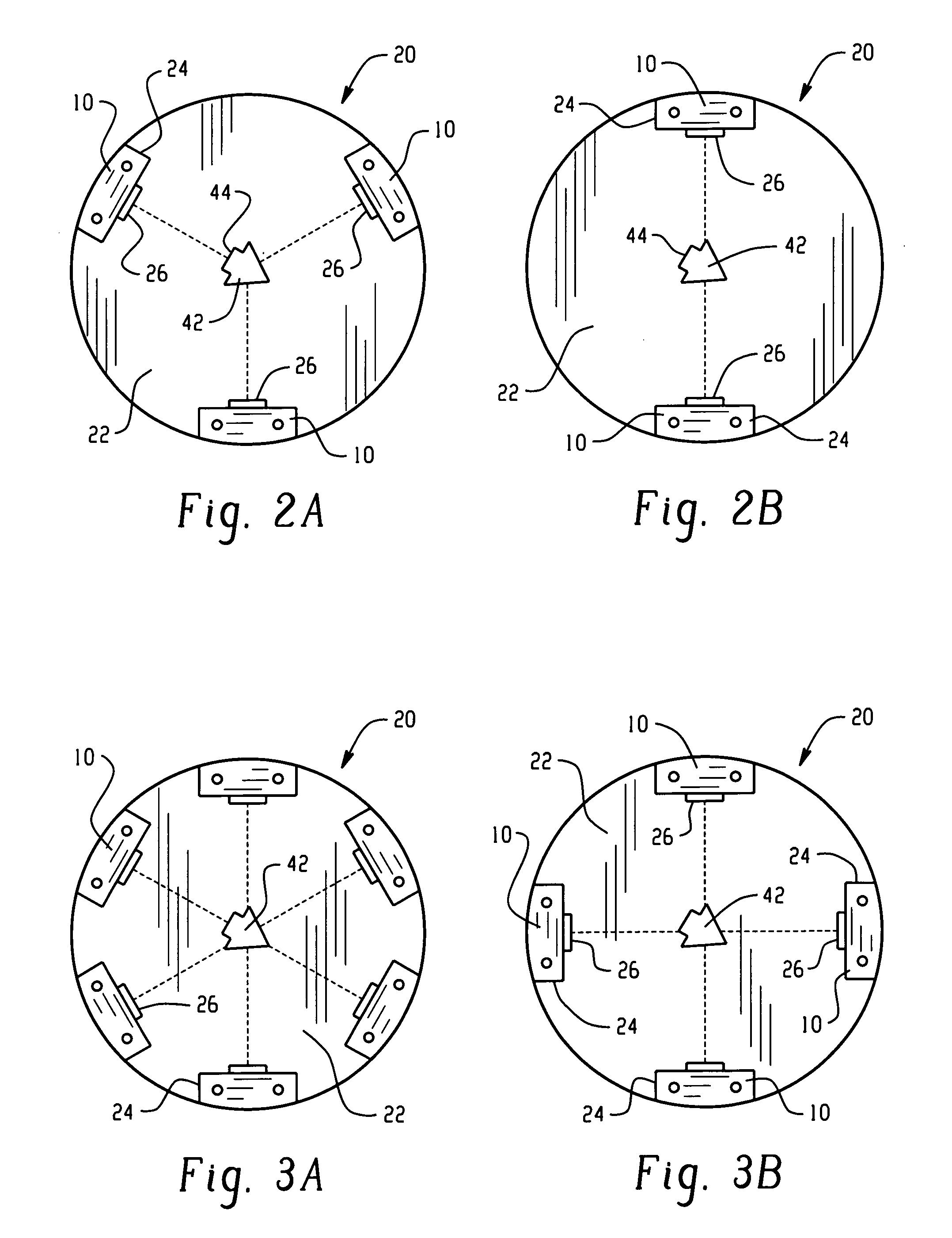
[0009]The figures generally indicate the features of the preferred embodiments, where it is understood and appreciated that like reference numerals are used to refer to like elements. As shown in FIG. 1A, a number of antenna elements 10 are provided for transmitting and receiving wireless signals over a plurality of wireless channels. The antenna elements 10 are configured so as to provide “antenna isolation” so that the signal from one antenna element 10 does not interfere with another antenna element 10. The “antenna element 10” can respectively refer either a single antenna or a pair of diversity antennas operating in conjunction.

[0010]In any event, as shown in FIG. 1A, an antenna element 10 includes either a single monopole antenna 12, or diversity pair of antennas 12. Each of these antenna elements 10 may be isolated from other antenna elements 10 by using an isolating component 14, which can be a metallic vane reflector, an RF absorber material or a suitable combination thereo...


PUM


Abstract

A removable antenna assembly and wireless access point including the same is disclosed in which a plurality of antenna elements are provided for transmitting and receiving wireless signals over a plurality of wireless channels. A sectorized mounting structure is provided for retaining each of the plurality of antenna elements substantially in an antenna isolation configuration, so as to enable simultaneous sectorized signal communication of the antenna elements over the wireless channels. A removable network interface is provided for selectively enabling a signal connection between a radio digital interface component and the plurality of antennas.

Description

BACKGROUND OF THE INVENTION[0001]The present system is directed to the field of radio communications, with particular applicability to the field of wireless networking, where mobile client devices such as wireless laptop and handheld computers are in radio communication with a network. In the field of wireless networking, it is desirable to operate a wireless local area network (WLAN) with multiple wireless channels, so as to increase throughput and thereby service a greater number of wireless clients. As a result, two-channel configurations are becoming the standard for wireless access point (AP) deployments, used to exchange signals between the network and the client. Such deployments typically include one channel in the 2.4 GHz range in accordance with the IEEE 802.11(b) or (g) protocols, and a single channel in the 5 GHz range in accordance with the IEEE 802.11(a) protocol. It is expected that throughput requirements will continue to rise and that dense wireless client user envi...

Claims


Application Information

Patent Timeline
Patent Type & Authority Patents(United States)
IPC IPC(8): H01Q1/24H01Q1/08H01Q1/52H01Q9/04H01Q9/30H01Q19/10H01Q21/00H01Q21/20H04L12/28
CPCH01Q1/088H01Q1/246H01Q1/523H01Q9/0407H01Q19/10H01Q21/205H01Q9/30H04W88/08H04W84/12
Inventor THEOBOLD, DAVID M.
Owner CISCO TECH INC
Why Eureka
Try Eureka