
Thermostat system with remote data averaging

a technology of remote data and thermostat system, applied in the field of thermostats, can solve the problems of complex system, additional cost, and the ability of the thermostat system to easily over- or under-condition a room

Active Publication Date: 2006-06-06
ROSEN TECH LLC
View PDF12 Cites 136 Cited by
  • Summary
  • Abstract
  • Description
  • Claims
  • Application Information

AI Technical Summary

Benefits of technology

[0010]In a second embodiment, remote sensors and occupancy detectors are associated as in the first embodiment. However, this second embodiment comprises transmission means that causes transmission of environmental sensor signals to the central control device with additional signals indicating whether the sensor signal originates from an occupied or non-occupied room. Transmission means may transmit continuously, periodically or upon the occurrence of a sensed event. The occupancy status of the room is determined by the input to the transmission means of the occupancy sensor. These remote sensor signals are transmitted to the central control device and stored in its memory as a table of data indicating environmental conditions of both occupied and un-occupied rooms. The values of this table are averaged in one of several selected modes to yield a control value. This control value more accurately reflects the overall desired environmental conditions of the rooms where user's are present.

Problems solved by technology

Unfortunately, zone control requires dedicated equipment for the zone or duct dampers or deflectors to direct conditioned air to the zone rooms.
This requires complexity and additional cost to the system.
The control value established by prior art thermostat systems can easily over- or under-condition a room where a user most desires environmental control.

Method used


Image

  • Thermostat system with remote data averaging
  • Thermostat system with remote data averaging
  • Thermostat system with remote data averaging

Examples


first embodiment

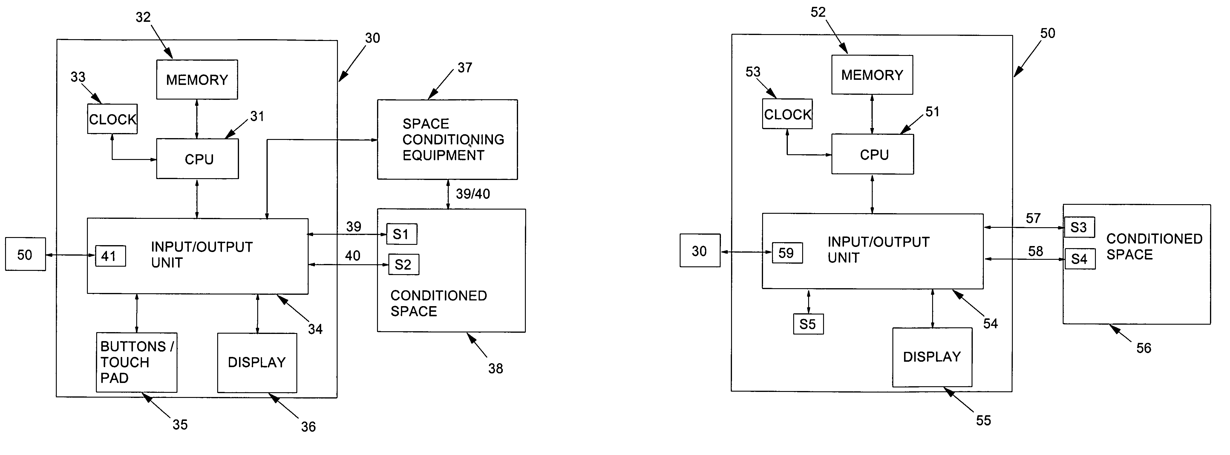
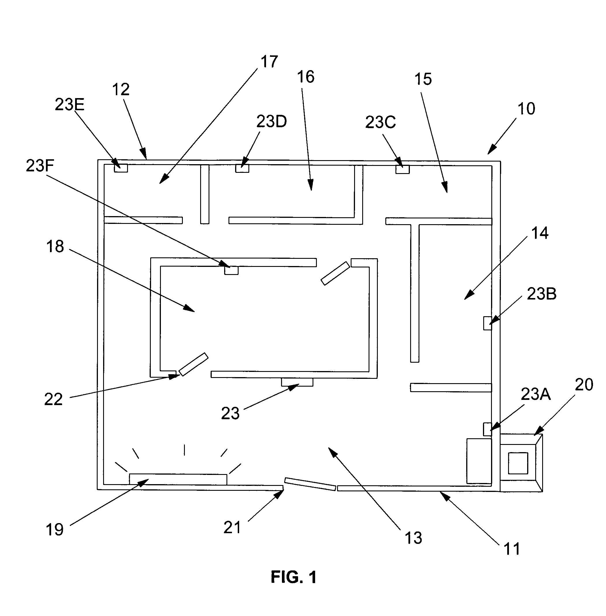
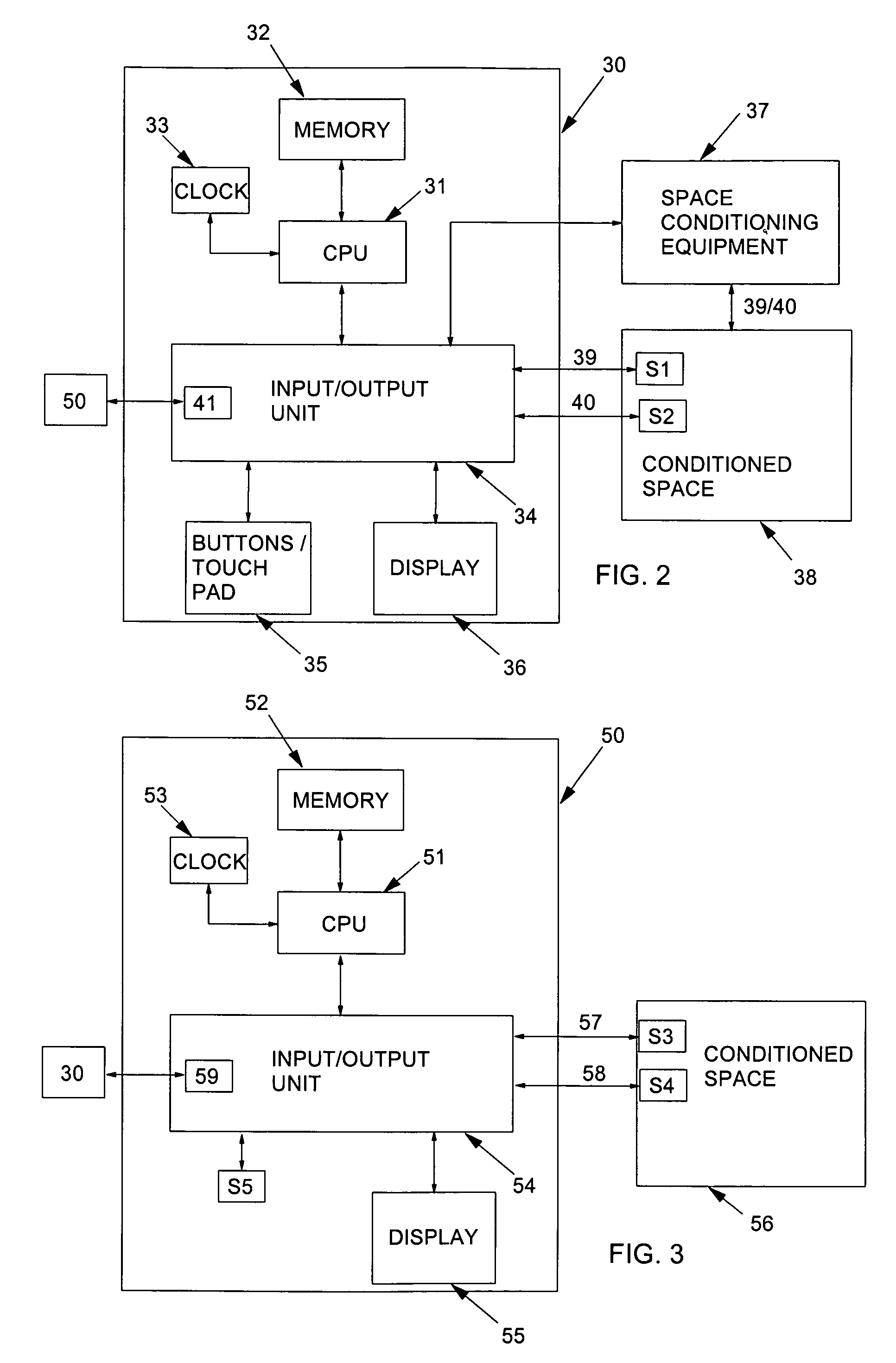
[0032]Consider now the invention referring to FIG. 4 as well as FIGS. 1, 2 and 3. Continuously or at one or more predetermined times of day (and / or on-demand if provided for in a sensor control program), occupancy sensor S4 determines whether or not its local conditioned space (i.e., a room) is occupied. An occupancy sensor S4 may detect motion in the room, the opening of doors 21 or 22, or the turning on of a light fixture 19, all of which indicate presence of a human occupant. Processor 50 comprises a sensor control program that determines whether occupancy sensor S4 has detected occupancy in conditioned space 56. If occupancy is not detected, the control program optionally waits a predetermined period of time before evaluating input from occupancy sensor S4 again or monitors such inputs continuously. If occupancy is detected, the sensor control program inquires to determine if an optional device motion sensor S5 has detected movement of the remote sensor from a resting or install...

second embodiment

[0033]Consider now the invention referring to FIG. 5 as well as FIGS. 1, 2 and 3. Continuously or at one or more predetermined times of day (and / or on-demand if provided for in a sensor control program), occupancy sensor S4 determines whether or not its local conditioned space (i.e., a room) is occupied. An occupancy sensor S4 may detect motion in the room, the opening of doors 21 or 22, or the turning on of a light fixture 19, all of which indicate presence of a human occupant. Processor 50 comprises a sensor control program that determines whether occupancy sensor S4 has detected occupancy in conditioned space 56. If occupancy is not detected, the sensor control program receives and transmits to the central control device 23 the signals (or values) from environmental sensor S3 with signals indicating that the sensor value is associated with a vacant room. The remote sensor optionally waits a predetermined period of time before evaluating input from occupancy sensor S4 again. If oc...


PUM


Abstract

A thermostat system according to the invention includes: a central control device (typically a programmable thermostat with a processor having: a CPU, real time clock and a memory for storing a control program and data information), multiple rooms comprising a conditioned space, environmental control equipment, and multiple environmental sensors capable of sensing an environmental condition (such as temperature, humidity, or other condition). The sensors are associated with transmission means, which control transmission of sensor signals, and occupancy sensors. Each sensor measures a local environmental condition. Occupancy sensors comprise infrared or other motion sensors, light detection sensors, door opening sensors, and other such sensors that detect the presence of humans in a room of the conditioned space where its associated sensor is located. Space conditioning equipment is activated by comparison of a setpoint to a control value averaged from values of environmental conditions in occupied rooms.

Description

FIELD OF THE INVENTION[0001]This invention relates to the art of thermostats and, more particularly, to a thermostat system incorporating a central control device receiving remote environmental sensing data from remote sensors.BACKGROUND OF THE INVENTION[0002]Thermostats have been used for many years as a temperature sensitive switch which controls heating and / or cooling equipment for conditioning a space in which the thermostat, or a temperature sensor connected to the thermostat, is placed. In the well known manner, a simple thermostat can be adjusted to establish a temperature set point such that, when the temperature in the conditioned space reaches the set point, the thermostat interacts with the heating and / or / cooling equipment to take suitable action to heat or cool the conditioned space as may be appropriate for the season.[0003]Modern thermostat systems, which take advantage of the ongoing rapid advances in electronic technology and circuit integration, have many features w...

Claims


Application Information

Patent Timeline
Patent Type & Authority Patents(United States)
IPC IPC(8): G05D23/00
CPCG05D23/1931F24F11/0034F24F11/30F24F2120/10F24F11/52F24F11/64
Inventor ROSEN, HOWARD
Owner ROSEN TECH LLC
Learn More