Submarine optical cable breakpoint location and disturbance location analysis method and system

A submarine optical cable and analysis method technology, applied in the direction of fault location, measuring device, optical instrument test, etc., can solve the problems of submarine optical cable damage, hinder the protection and maintenance of submarine optical cable, etc., and achieve fast and accurate judgment, less calculation time, and judgment accurate effect

Active Publication Date: 2019-10-22
GUANGDONG POWER GRID CO LTD +1
View PDF8 Cites 6 Cited by
  • Summary
  • Abstract
  • Description
  • Claims
  • Application Information

AI Technical Summary

Problems solved by technology

However, these traditional methods cannot detect the disturbance or damage of the submarine optica...

Method used


Image

  • Submarine optical cable breakpoint location and disturbance location analysis method and system
  • Submarine optical cable breakpoint location and disturbance location analysis method and system
  • Submarine optical cable breakpoint location and disturbance location analysis method and system

Examples


Embodiment 1

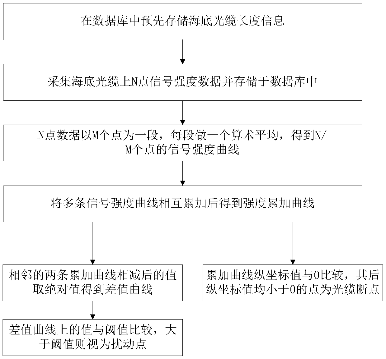
[0056] Such as Figure 1 to Figure 5 Shown in this embodiment is an embodiment of the submarine optical cable breakpoint position and disturbance position analysis method, including the following steps:

[0057] S10. Pre-store the submarine optical cable length information in the database;

[0058] S20. Collect n sets of signal strength data containing N signal strength data points on the submarine optical cable and store them in the database;

[0059] S30. The signal strength data of N points takes M points as a section and performs arithmetic mean to obtain a signal strength curve containing N / M data points, wherein: M∈[1,N];

[0060] S40. Among the n signal strength curves, every m signal strength curves are mutually accumulated to obtain n / m strength accumulation curves;

[0061] S50. compare the value on the cumulative curve described in step S40 with the value 0: if the values ​​of all points after the X point are all less than 0, then it can be judged that the X point...

Embodiment 2

[0096] Such as Figure 5 Shown is that this embodiment is the embodiment of the submarine optical cable breakpoint position and disturbance position analysis system, including the second optical fiber coupler, balance detector, logarithmic detector, data acquisition card and PC connected in sequence, the second The input end of the fiber coupler is connected with the first input loop and the second input loop:

[0097] The first input loop includes a signal-connected light source and a first fiber coupler, and the first fiber coupler is connected to the first input end of the second fiber coupler;

[0098] The second input loop includes a light source connected in sequence, a first optical fiber coupler, an acousto-optic modulator, an optical fiber amplifier, and an optical gyrator. The optical gyrator is connected to the second input end of the second optical fiber coupler, and the acousto-optic modulator Connected with a radio frequency signal generator, the optical gyrator...


PUM


Abstract

The present invention belongs to the technical field of power grid monitoring and relates to a submarine optical cable breakpoint location and disturbance location analysis method and system. The method comprises the following steps that: a data acquisition card is adopted to acquire signal strength data on an optical cable, multiple-point data averaging is performed on the acquired signal strength data, so that signal strength curves are obtained; the plurality of signal strength curves are accumulated; the absolute value of the difference of strength accumulation curves is calculated, so that a difference value curve is obtained, every two adjacent signal strength curves being accumulated to obtain one strength accumulation curve; values on the difference value curve are compared with athreshold value, points on the difference value curve, which exceed the threshold value, are judged as submarine cable disturbance events, if events occur in all points behind a certain point, it canbe determined that the point is an optical cable breakpoint; and points which are located behind the point on the strength accumulation curves and have vertical coordinates smaller than 0, are disturbance points. According to the submarine optical cable breakpoint location and disturbance location analysis method and system of the invention, the signals are accumulated in space and in time, so that a high signal-to-noise ratio is obtained; two adjacent groups of accumulated signals are subtracted from each other, so that the disturbance condition of the submarine optical cable can be judged,and the breakpoint position of the submarine optical cable is obtained. Therefore, with the method and system adopted, the breakpoint position of the optical cable can be judged when the disturbance of the optical cable is detected, and judgment is accurate, and calculation time is short.

Description

technical field [0001] The invention relates to the technical field of power grid monitoring, and more specifically, to a method and system for analyzing breakpoint positions and disturbance positions of submarine optical cables. Background technique [0002] The existence and development of submarine optical cables have a history of more than 160 years, and the use of submarine optical cables has exceeded a hundred years. Due to the high cost of the submarine optical cable, the special layout environment, the high repair and maintenance costs and long cycle after the submarine cable is damaged, and the high cost of power outage and production stoppage caused by the submarine optical cable failure, it is urgent to use the submarine optical cable online monitoring technology to monitor the submarine cable in real time. Operational monitoring. Traditional submarine cable protection thinking mainly focuses on protection during construction and rapid repair after failure. The m...

Claims


Application Information

Patent Timeline
IPC IPC(8): G01M11/00G01R31/08
CPCG01M11/30G01R31/088
Inventor 王升孙廷玺谢峰赵尊慧方义治胡孝晖仇炜吴伟文崔江静鲁晓一
Owner GUANGDONG POWER GRID CO LTD
Why Eureka
Try Eureka