
Differential output instrument amplifier

An instrumentation amplifier, differential output technology, applied in sensors, medical science, diagnosis, etc., can solve the problem of not being able to meet the full differential, and achieve the effect of improving the signal-to-noise ratio, anti-interference ability, and strong anti-interference ability

Pending Publication Date: 2021-08-06
北京脑陆科技有限公司
View PDF0 Cites 0 Cited by
  • Summary
  • Abstract
  • Description
  • Claims
  • Application Information

AI Technical Summary

Problems solved by technology

However, the existing instrumentation amplifiers are all single-ended output, which cannot meet the needs of full differential

Method used


Image

  • Differential output instrument amplifier

Examples


Embodiment Construction

[0015] The core of the present invention is to provide a meter amplifier for differential output to achieve differential output, improve signal-to-noise ratio, and anti-interference capability.

[0016] In order to better understand the present invention, the technical solutions in the embodiments of the present invention will be described in connection with the drawings in the embodiments of the present invention, and the embodiments described herein will be clearly understood. It is a part of the embodiments of the present invention, not all of the embodiments. Based on the embodiments of the present invention, there are all other embodiments obtained without making creative labor without making creative labor premises.

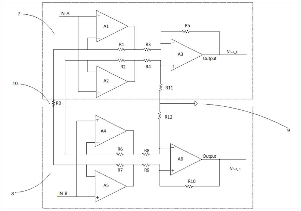
[0017] figure 1 A meter amplifier structure for a differential output provided by the embodiment of the present invention, figure 1 In the middle, the mark 7 represents the first three-acting instrumentation amplifier, and the mark 8 represents the second thre...


PUM


Abstract

The invention discloses a differential output instrumentation amplifier. The amplifier comprises a first three-operational-amplifier instrumentation amplifier, a second three-operational-amplifier instrumentation amplifier and a gain resistor R0; the first three-operational-amplifier instrumentation amplifier comprises operational amplifiers A1, A2 and A3 and resistors R1, R2, R3, R4, R5 and R11, and the second three-operational-amplifier instrumentation amplifier comprises operational amplifiers A4, A5 and A6 and resistors R6, R7, R8, R9, R10 and R12; and the first three-operational-amplifier instrument amplifier and the second three-operational-amplifier instrument amplifier are in cross connection, an inverting input end of the operational amplifier A1 is connected with an inverting input end of the operational amplifier A5 through the R0, and an inverting input end of the operational amplifier A2 is connected with an inverting input end of the operational amplifier A4. Therefore, the differential output instrument amplifier realizes differential output.

Description

Technical field [0001] The present invention relates to the field of circuit technology, and more particularly to a meter amplifier for differential output. Background technique [0002] EEG signal represents EEG, EEG is the overall reflection of cerebral neural cell electrophysiological activities in the cerebral cortex or scalp surface. A large number of physiological and disease information is included in the eElectronic signal, and is widely used in brain activity analysis and disease diagnosis. However, since the EEG signal is low, the randomness and non-linearity are strong, it is extremely susceptible to other signals during the acquisition process, and increases the difficulty of subsequent analysis. [0003] Since the ecpoC signal is the electrode collected by the cerebral cortical neuronal group and the electrode collected by the cortex, cerebrospinal fluid, epidural, skull and scalp and scalp, which is easily contaminated, it is likely to make EEG implied The brain fun...

Claims


Application Information

Patent Timeline
Patent Type & Authority Applications(China)
IPC IPC(8): A61B5/369A61B5/372
Inventor 卢树强夏威王晓岸
Owner 北京脑陆科技有限公司
Learn More