A method and system for analyzing breakpoint position and disturbance position of submarine optical cable
What is AI technical title?
AI technical title is built by Patsnap AI team. It summarizes the technical point description of the patent document.
A submarine optical cable and analysis method technology, applied in the direction of fault location, measuring device, optical instrument test, etc., can solve the problems of submarine optical cable damage, hinder the protection and maintenance of submarine optical cable, etc., achieve the effect of less calculation time and accurate judgment
Active Publication Date: 2021-08-10
GUANGDONG POWER GRID CO LTD +1
View PDF8 Cites 0 Cited by
Summary
Abstract
Description
Claims
Application Information
AI Technical Summary
This helps you quickly interpret patents by identifying the three key elements:
Problems solved by technology
Method used
Benefits of technology
Problems solved by technology
However, these traditional methods cannot detect the disturbance or damage of the submarine optical cable in the first place, which hinders the protection and maintenance of the submarine optical cable.
Method used
Image
Click on the blue label to locate the original text in one second.
Reading with bidirectional positioning of images and text.
Examples
Embodiment 1
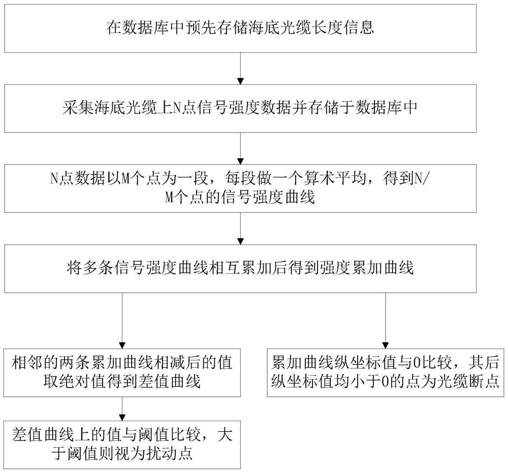
[0047] like Figure 1 to Figure 5 Shown in this embodiment is an embodiment of the submarine optical cable breakpoint position and disturbance position analysis method, including the following steps:
[0048] S10. Pre-store the submarine optical cable length information in the database;
[0049] S20. Collect n sets of signal strength data containing N signal strength data points on the submarine optical cable and store them in the database;
[0050] S30. The signal strength data of N points takes M points as a section and performs arithmetic mean to obtain a signal strength curve containing N / M data points, wherein: M∈(1, N);
[0051] S40. Among the n signal strength curves, every m signal strength curves are mutually accumulated to obtain n / m strength accumulation curves;
[0052] S50. compare the value on the cumulative curve described in step S40 with the value 0: if the values of all points after the X point are all less than 0, then it can be judged that the X point is ...
Embodiment 2
[0078] like Figure 5 Shown is that this embodiment is the embodiment of the submarine optical cable breakpoint position and disturbance position analysis system, including the second optical fiber coupler, balance detector, logarithmic detector, data acquisition card and PC connected in sequence, the second The input end of the fiber coupler is connected with the first input loop and the second input loop:
[0079] The first input loop includes a signal-connected light source and a first fiber coupler, and the first fiber coupler is connected to the first input end of the second fiber coupler;
[0080] The second input loop includes a light source connected in sequence, a first optical fiber coupler, an acousto-optic modulator, an optical fiber amplifier, and an optical gyrator. The optical gyrator is connected to the second input end of the second optical fiber coupler, and the acousto-optic modulator Connected with a radio frequency signal generator, the optical gyrator is...
PUM
Abstract
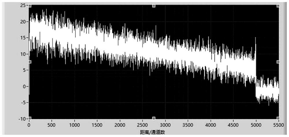
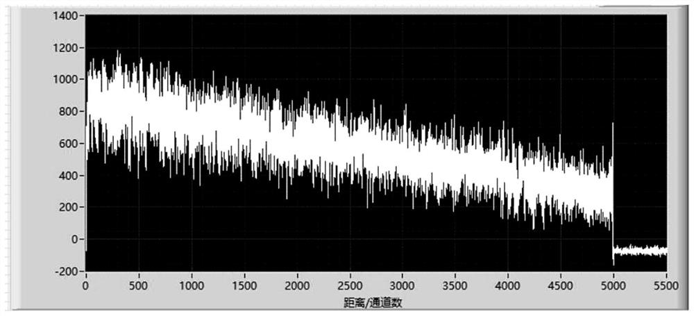
The present invention relates to the technical field of power grid monitoring, and more specifically, to a method and system for analyzing the breakpoint position and disturbance position of a submarine optical cable, including: using a data acquisition card to collect signal strength data on the optical cable, and determining the intensity of the collected information The signal strength curve is obtained after the point data is averaged; the multiple signal strength curves are accumulated; the difference curve is obtained by subtracting the value of the intensity accumulation curve obtained by subtracting two adjacent accumulated strength curves; the value on the difference curve Compared with the threshold value, the point on the difference curve that exceeds the threshold value is judged as a submarine cable disturbance event. When events occur at all points after a certain point, it can be judged that the point is a breakpoint of the optical cable; Points whose coordinate values are all less than 0 are disturbance points. The invention accumulates the signals in space and time to obtain a strong signal-to-noise ratio, and judges the disturbance on the submarine optical cable by subtracting the two sets of accumulated signals before and after to obtain the breakpoint position of the submarine optical cable. At the same time, the position of the breakpoint of the optical cable can be judged, and the judgment is accurate and the calculation time is small.
Description
technical field [0001] The invention relates to the technical field of power grid monitoring, and more specifically, to a method and system for analyzing breakpoint positions and disturbance positions of submarine optical cables. Background technique [0002] The existence and development of submarine optical cables have a history of more than 160 years, and the use of submarine optical cables has exceeded a hundred years. Due to the high cost of the submarine optical cable, the special layout environment, the high repair and maintenance costs and long cycle after the submarine cable is damaged, and the high cost of power outage and production stoppage caused by the submarine optical cable failure, it is urgent to use the submarine optical cable online monitoring technology to monitor the submarine cable in real time. Operational monitoring. Traditional submarine cable protection thinking mainly focuses on protection during construction and rapid repair after failure. The m...
Claims
Application Information
Patent Timeline
Application Date:The date an application was filed.
Publication Date:The date a patent or application was officially published.
First Publication Date:The earliest publication date of a patent with the same application number.
Issue Date:Publication date of the patent grant document.
PCT Entry Date:The Entry date of PCT National Phase.
Estimated Expiry Date:The statutory expiry date of a patent right according to the Patent Law, and it is the longest term of protection that the patent right can achieve without the termination of the patent right due to other reasons(Term extension factor has been taken into account ).
Invalid Date:Actual expiry date is based on effective date or publication date of legal transaction data of invalid patent.

