Hydraulic controller for construction machine

a construction machine and hydraulic controller technology, applied in the direction of fluid couplings, servomotors, couplings, etc., can solve the problems of poor workability, delay in working cycle time, and insufficient utilization of engine horsepower, and achieve the effect of increasing the operation speed of the boom

Active Publication Date: 2006-06-13
KOBELCO CONSTR MASCH CO LTD
View PDF29 Cites 26 Cited by
  • Summary
  • Abstract
  • Description
  • Claims
  • Application Information

AI Technical Summary

Benefits of technology

[0009]Accordingly, an object of the present invention is to provide a hydraulic controller for construction machine that enables synchronization between boom raising speed and rotating speed during a raising and rotating operation by distributing discharge oil from pumps optimally between a boom cylinder and a rotating motor.
[0012]In accordance with the present invention, at the start of the combined operation of boom raising and rotating, the discharge flow rate of the first pump becomes higher by a predetermined amount whereby discharge oil is supplied preferentially to the boom, which allows an increase in the operation speed of the boom. When the rotation has reached the steady rotating state, a rotational working pressure decreases and there occurs a pressure difference from the boom working pressure. As this pressure difference increases, the difference in discharge flow rate decreases, and when the boom has reached a predetermined height by the boom raising operation, discharge oil is supplied (distributed) preferentially to the rotation side. Therefore, it is possible to distribute discharge oil from the pumps optimally between the boom cylinder and the rotating motor during the raising and rotating operation, which enables synchronization between boom raising speed and rotating speed.

Problems solved by technology

Thus, the engine horsepower cannot be fully utilized, resulting in a delay in working cycle time and therefore poor workability.

Method used


Image

  • Hydraulic controller for construction machine
  • Hydraulic controller for construction machine
  • Hydraulic controller for construction machine

Examples


Embodiment Construction

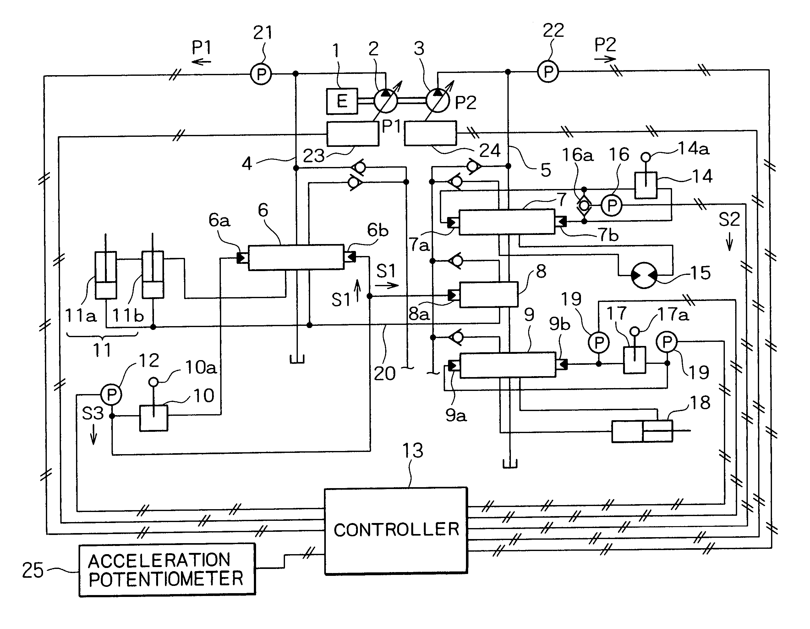
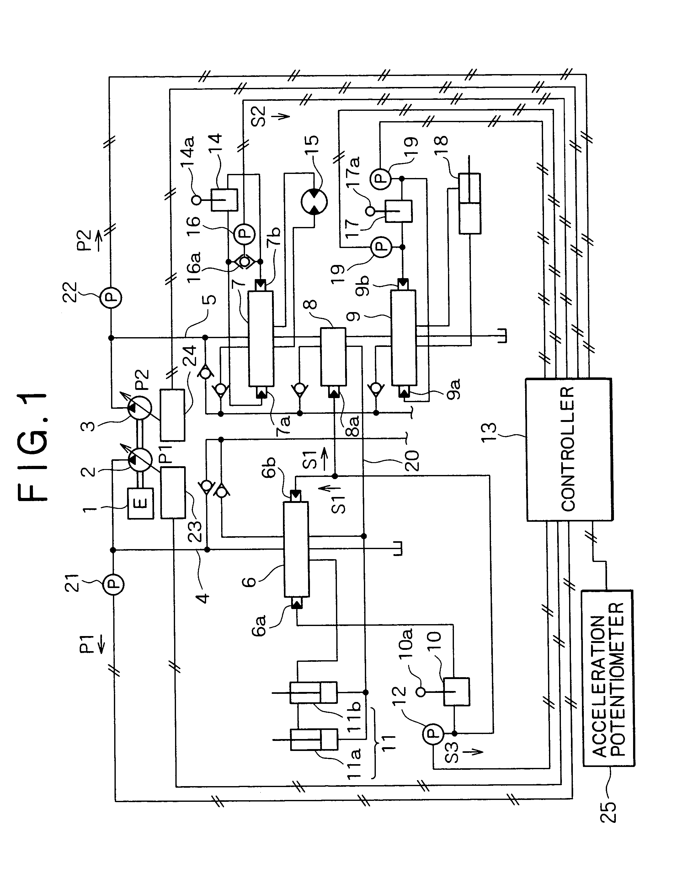
[0025]The present invention is directed to a hydraulic pressure control circuit for construction machine, wherein there are provided regulators for each of the first and second pumps of two series of variable capacity hydraulic pumps, each of the regulators being controlled, detecting a discharge pressure of each pump, in such a manner that one of the pumps absorbs a part of torque while the other thereof absorbs the remaining torque, and wherein a boom raising operation causes pressure oil from the first and second pumps to be joined together and then supplied to a boom cylinder, while also a rotating operation of an upper rotating body as rotating body causes pressure oil from the second pump to be supplied to a rotating motor, the hydraulic pressure control circuit comprising a boom raise detection means for detecting a boom raising operation, a rotation detection means for detecting a rotating operation, a first pump pressure detection means for detecting a discharge pressure of...


PUM


Abstract

In a hydraulic controller for construction machine according to the present invention, wherein there are provided regulators for each of a first and a second capacity variable hydraulic pump, each of the regulators being controlled, detecting the discharge pressure of each pump, in such a manner that one of the pumps absorbs a part of torque while the other thereof absorbs the remaining torque, and wherein a boom raising operation causes pressure oil from the pumps to be joined together and then supplied to a boom cylinder, while also a rotating operation causes pressure oil from the second pump to be supplied to a rotating motor, is provided a flow rate distribution controller adapted to control the regulators in such a manner that a difference in flow rate is provided between the pumps so that the first pump shows a higher flow rate at the start of a combined operation of raising and rotating, and that, on a steady rotating state which results in an increase in the discharge pressure difference between the pumps, the difference in flow rate is reduced. This enables pump horsepower to be distributed optimally between the boom cylinder and rotating motor during the raising and rotating operation.

Description

BACKGROUND OF THE INVENTION[0001]1. Field of the Invention[0002]The present invention relates to a hydraulic controller for a construction machine such as a hydraulic excavator.[0003]2. Description of the Related Art[0004]In hydraulic excavator comprising two series of variable capacity pumps and regulators for each thereof, engine overload is prevented not only by changing the flow rate of the first pump according to the load thereon but also by detecting the load on the second pump, operating the pumps in accordance with each other, and then controlling the total horsepower of the pumps.[0005]There are two cases: the first where working oil from each pump is supplied to each of actuators arranged respectively in two hydraulic systems, and the second where working oil from both pumps is joined together to be supplied such as in the case of a combined operation of the actuators, one case of which being selected appropriately according to actuators to be driven.[0006]To be more concr...

Claims


Application Information

Patent Timeline
Patent Type & Authority Patents(United States)
IPC IPC(8): F16D31/02E02F9/22F15B11/00F15B11/17
CPCE02F9/2235E02F9/2296E02F9/2292E02F9/2242
Inventor OKA, HIDEKAZUYAMASHITA, KOJISENOO, SABURO
Owner KOBELCO CONSTR MASCH CO LTD
Why Eureka
Try Eureka