Split-flow-type flow sensor device

a flow sensor and split-flow technology, which is applied in the direction of measurement devices, volume/mass flow measurement, instruments, etc., can solve the problems of affecting the accuracy of measurement, and disordered gas flow in the flow passage, so as to facilitate the assembly of the split-flow-type flow sensor apparatus, facilitate the deflection of gas flow, and improve the accuracy of measuremen

Inactive Publication Date: 2006-06-13
KEYENCE
View PDF7 Cites 83 Cited by
  • Summary
  • Abstract
  • Description
  • Claims
  • Application Information

AI Technical Summary

Benefits of technology

[0010]It is therefore an object of the invention to provide a split-flow-type flow sensor apparatus having a new structure for making possible miniaturization and cost reduction while maintaining high measurement accuracy and measurement stability.
[0016]The first configuration of the invention makes it possible to miniaturize a split-flow-type flow sensor apparatus while maintaining high measurement accuracy and measurement stability. The first rectification member has a function of mainly uniforming the radial flow distribution in the main flow passage before diversion, namely, the flow distribution in the cross section of the flow passage. Particularly, if the shape of the pipe line on the upstream side of the split-flow-type flow sensor apparatus is not linear and is bent (for example, bent like a letter L) or if the diameter of the pipe line changes, deflection of gas flow (drift) easily occurs, in which case the effect of the first rectification member is large. The second rectification member has a function of performing rectification upstream from the thermal flow sensor in the bypass flow passage and suppressing gas flow disorder in the proximity of the thermal flow sensor. Particularly, if the gas flow velocity is high or the cross section of the bypass flow passage is large, the effect of the second rectification member is large.
[0017]According to the second configuration of the invention, the bypass flow passage is provided by one module, whereby assembling the split-flow-type flow sensor apparatus is facilitated, contributing to cost reduction of the apparatus. Maintainability of the apparatus is also improved.
[0018]According to the third configuration of the invention, the entrance of the bypass flow passage is positioned roughly at the center of the cross section of the main flow passage. Therefore, gas at the center where comparatively stable gas flow occurs rather than in the vicinity of the wall face of the pipe line where the effect of gas flow disorder or drift is easily received can be introduced into the bypass flow passage. Consequently, the flow quantity of gas flowing through the bypass flow passage easily becomes stable and the stability of flow measurement of the thermal flow sensor is improved.
[0020]According to the fifth configuration of the invention, the second rectification member includes a plurality of mesh plates that can be placed in a short space in the flow passage direction can be formed. The rectification effect is enhanced by the plurality of mesh parts put on the top of each other with a given gap. In the bypass flow passage module formed comparatively small, it is difficult to provide a long space in the flow passage direction upstream from the thermal flow sensor and therefore such a structure is appropriate for the second rectification member. Since a plurality of mesh plates need only to be put on the top of each other without the intervention of a spacer, it becomes easy to assemble the apparatus.

Problems solved by technology

In the flow sensor apparatus using the small thermal flow sensor as described above, if the flow quantity of gas increases, the gas flow in the flow passage tends to be disordered and the measurement accuracy tends to be degraded.

Method used


Image

  • Split-flow-type flow sensor device
  • Split-flow-type flow sensor device
  • Split-flow-type flow sensor device

Examples


Embodiment Construction

[0038]Referring now to the accompanying drawings, there are shown preferred embodiments of the invention.

[0039]FIG. 12 is an external view to show the whole configuration of a split-flow-type flow sensor apparatus according to an embodiment of the invention. The split-flow-type flow sensor apparatus of the embodiment includes a head section 31 and an amplification section 32 which are connected by an electric cable 27. The amplification section 32 can be further connected to an external machine (not shown) via an electric cable 10.

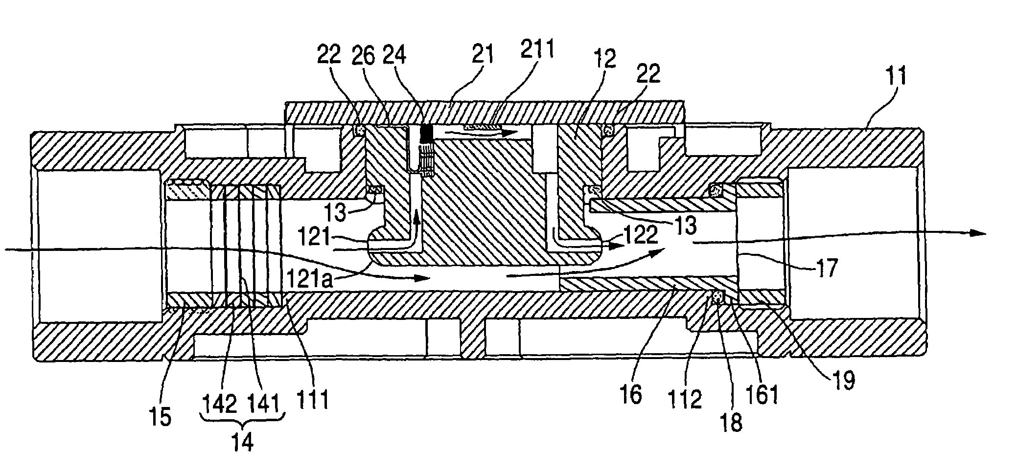
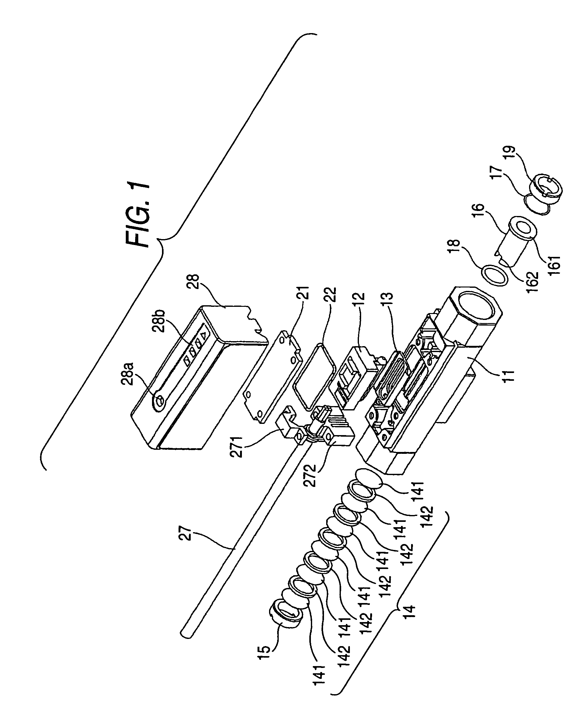
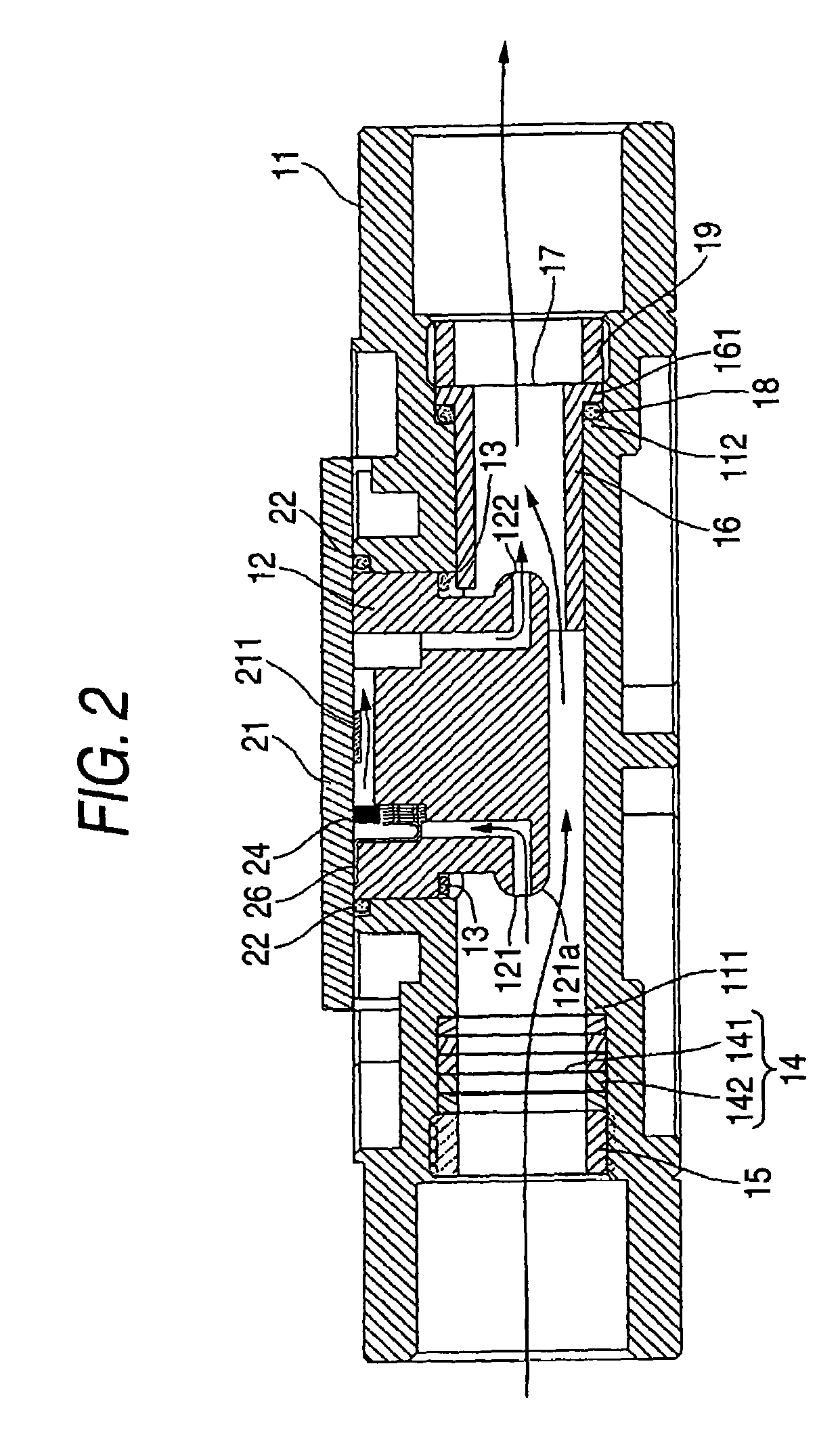
[0040]FIG. 13 is an external view to show the appearance of the head section of the split-flow-type flow sensor apparatus according to the embodiment of the invention. FIG. 1 is an exploded view of the head section of the split-flow-type flow sensor apparatus, and FIG. 2 is a sectional view of the main part of the head section of the split-flow-type flow sensor apparatus. The split-flow-type flow sensor apparatus includes a main flow passage member (main f...


PUM


Abstract

A split-flow-type flow sensor apparatus includes a main flow passage and a bypass flow passage, wherein a thermal flow sensor is placed on the wall face of the bypass flow passage. A first rectification member is placed upstream from a diversion part to the bypass flow passage in the main flow passage, and a second rectification member is placed upstream from the thermal flow sensor in the bypass flow passage. A bypass flow passage module is inserted into an opening formed on a side of a main flow passage module. The side opening of the main flow passage module is sealed and an entrance and an exit of the bypass flow passage are positioned in the main flow passage.

Description

[0001]This application claims foreign priority based on Japanese patent application JP 2004-043724, filed on Feb. 19, 2004 and Japanese patent application JP 2004-112536, filed on Apr. 6, 2004, the contents of which are incorporated herein by reference in its entirety.BACKGROUND OF THE INVENTION[0002]1. Field of the Invention[0003]This invention relates to a split-flow-type flow sensor apparatus including a main flow passage and a bypass flow passage with a thermal flow sensor placed on the wall face of the bypass flow passage.[0004]2. Description of the Related Art[0005]Flow sensors for measuring the flow quantity of gas include a sensor called a thermal flow sensor. With the sensor, a resistor such as a platinum wire is exposed to a gas flow and the degree of cooling heat produced when an electric current is allowed to flow into the resistor by the gas flow is detected, whereby the gas flow quantity is measured.[0006]In recent years, a small thermal flow sensor formed with a plati...

Claims


Application Information

Patent Timeline
Patent Type & Authority Patents(United States)
IPC IPC(8): G01F1/68G01F1/00G01F1/684G01F5/00
CPCG01F5/00G01F1/6842
Inventor KANOUDA, SOUHEITAKAYANAGI, SUSUMUHAMA, KIYOSHI
Owner KEYENCE
Why Eureka
Try Eureka