Sling bow

a sling bow and arrow technology, applied in the field of sling bows, can solve the problems of drawbacks of each device, and achieve the effect of convenient assembly and us

Inactive Publication Date: 2006-06-13
TEAGUE MARSHALL
View PDF15 Cites 16 Cited by
  • Summary
  • Abstract
  • Description
  • Claims
  • Application Information

AI Technical Summary

Benefits of technology

[0009]Still another object of the present invention is to provide a device which is easy to assemble and use.

Problems solved by technology

However, each of the devices has drawbacks.

Method used


Image

  • Sling bow
  • Sling bow
  • Sling bow

Examples


Embodiment Construction

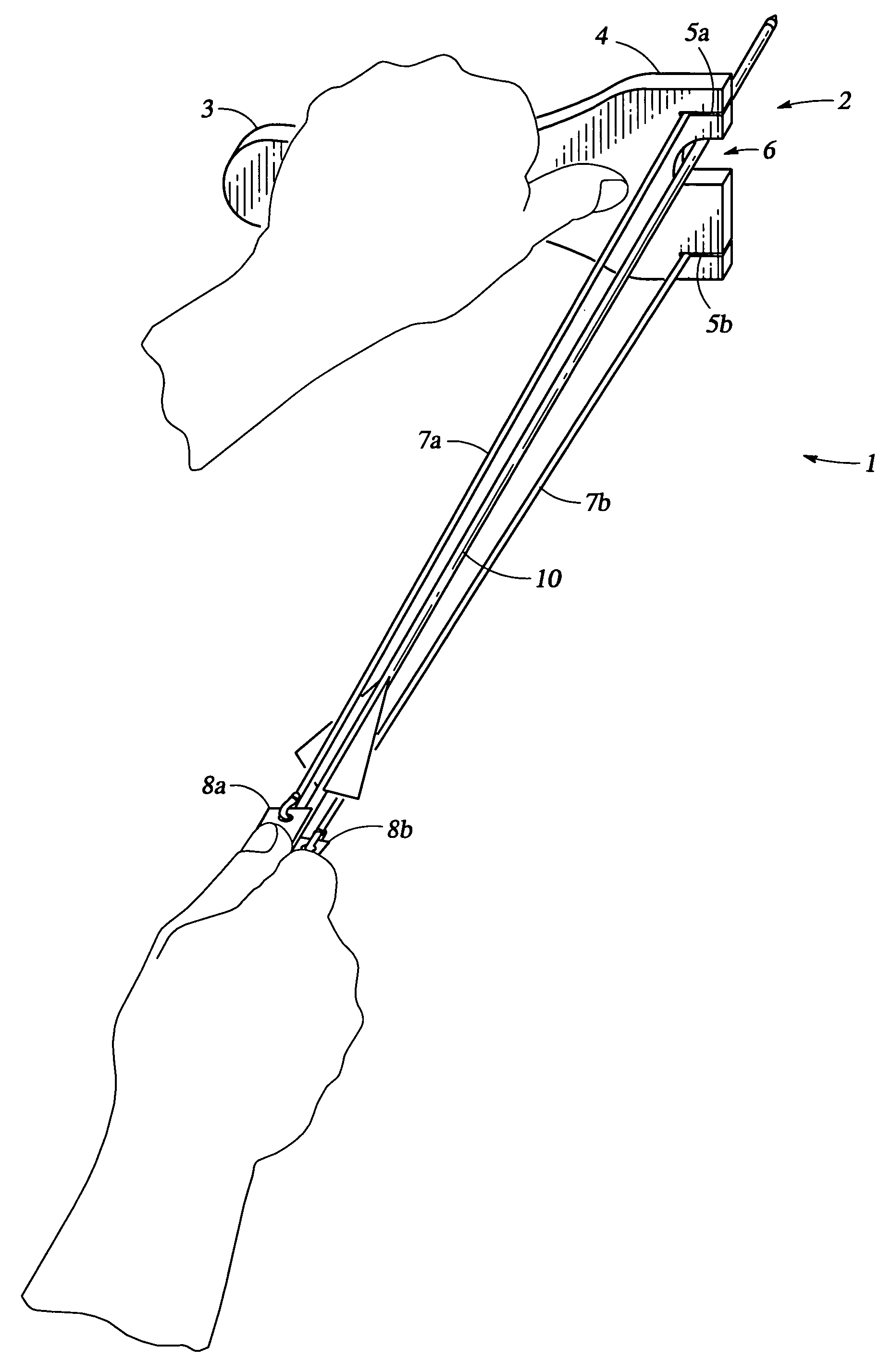
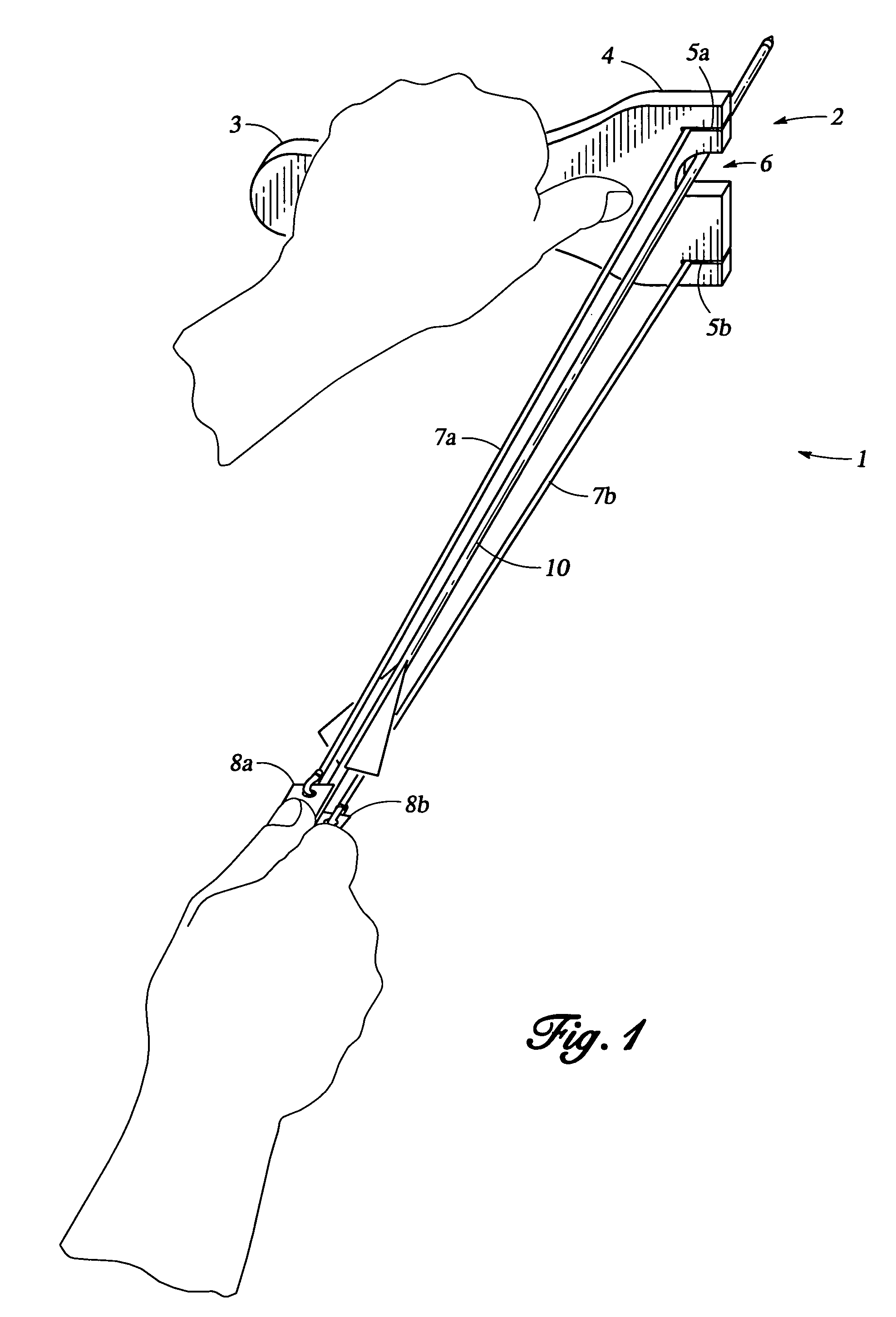
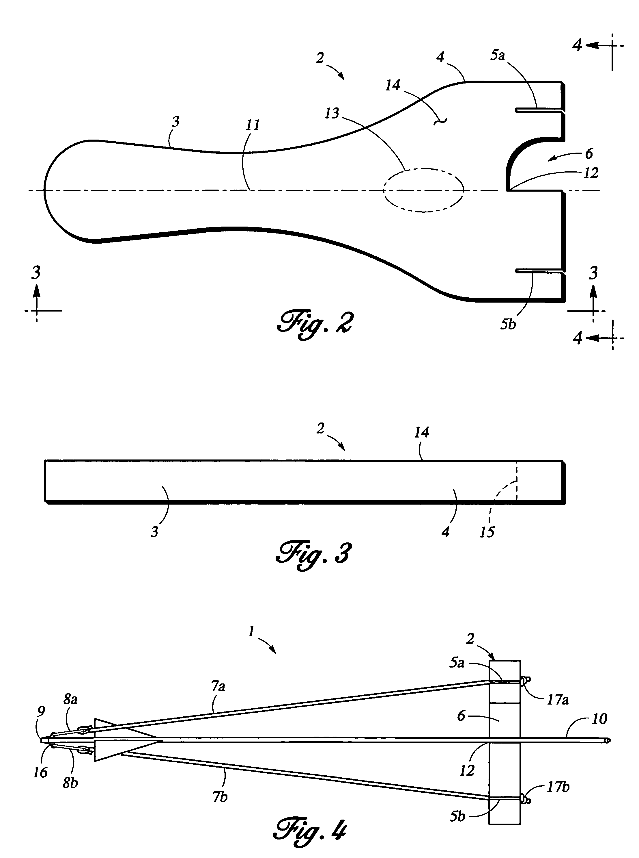
[0014]As shown in FIG. 1, the sling bow 1 of the present invention has a frame 2 which is generally constructed from wood, or rigid plastic; it can also be made from a metal such as aluminum. The frame 2 is shaped with a handle 3 and a Y-shaped end 4 having extensions into which slots 5a, 5b are cut. An off-center arcuate notch 6, shaped like a quarter circle, is cut into the Y-shaped end 4 between the slots 5a, 5b; it is used to center an arrow 10 when the shooter prepares to launch it. One end of each strap 7a, 7b is inserted into one of the slots 5a, 5b, and the other end of each strap 7a, 7b is attached to one of the grip portions 8a, 8b. The straps 7a, 7b are made from an elastic, resilient material such as surgical rubber, and the grip portions 8a, 8b are generally made from a flexible material, such as leather. The shape of the notch 6 and the symmetry of the slots 5a, 5b allow a shooter to launch an arrow 10 with great accuracy.

[0015]When shooting an arrow 10, the shooter ho...


PUM


Abstract

A sling bow having a frame shaped with a handle and a Y-shaped end into which an off-center, quarter-circle shaped notch is cut, against the side of which the shaft of a conventional arrow rests before it is launched. Slots cut in the extensions of the Y-shaped end hold the ends of two straps, the opposite ends of each being connected to gripping portions which are connected to each other with a bent wire, against which the nock of the arrow is placed. The shape of the notch and the symmetry of the slots allow a shooter to launch a conventional arrow accurately.

Description

BACKGROUND OF THE INVENTION[0001]The present invention relates to a compact, hand-held device for launching arrows.[0002]The prior art discloses a number of devices for shooting conventional arrows, several which use a slingshot-like frame rather than a bow. The devices range from the simple to the complex. For a device to be useful, it must be able to launch arrows accurately. The prior art devices take different approaches, from using tubes through which the arrows fly to having retractable arrow rests. However, each of the devices has drawbacks.[0003]There is a need for a compact sling bow which is easy to use, but which can still accurately launch conventional arrows. The sling bow should be durable, yet lightweight. The sling bow should be useable by both right-handed and left-handed sportsmen.SUMMARY OF THE INVENTION[0004]The present invention has a flat, generally Y-shaped frame formed with a handle on one end and the other end having two extensions separated by an off-center...

Claims


Application Information

Patent Timeline
Patent Type & Authority Patents(United States)
IPC IPC(8): F41B3/02
CPCF41B3/02
Inventor TEAGUE, MARSHALL
Owner TEAGUE MARSHALL
Why Eureka
Try Eureka