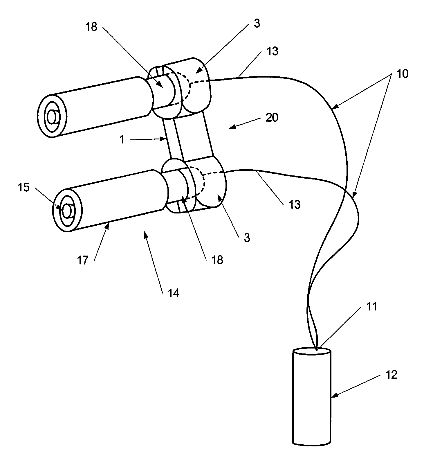
Epicardial pacer extension cable system

a technology of extension cable and epicardial cord, which is applied in the direction of epicardial electrode, coupling device connection, therapy, etc., can solve the problems of equipment damage, short circuit, and possible patient injury, so as to reduce the risk of short circuit and harm to the patient

Active Publication Date: 2006-06-13
REMINGTON MEDICAL
View PDF18 Cites 20 Cited by
  • Summary
  • Abstract
  • Description
  • Claims
  • Application Information

AI Technical Summary

Benefits of technology

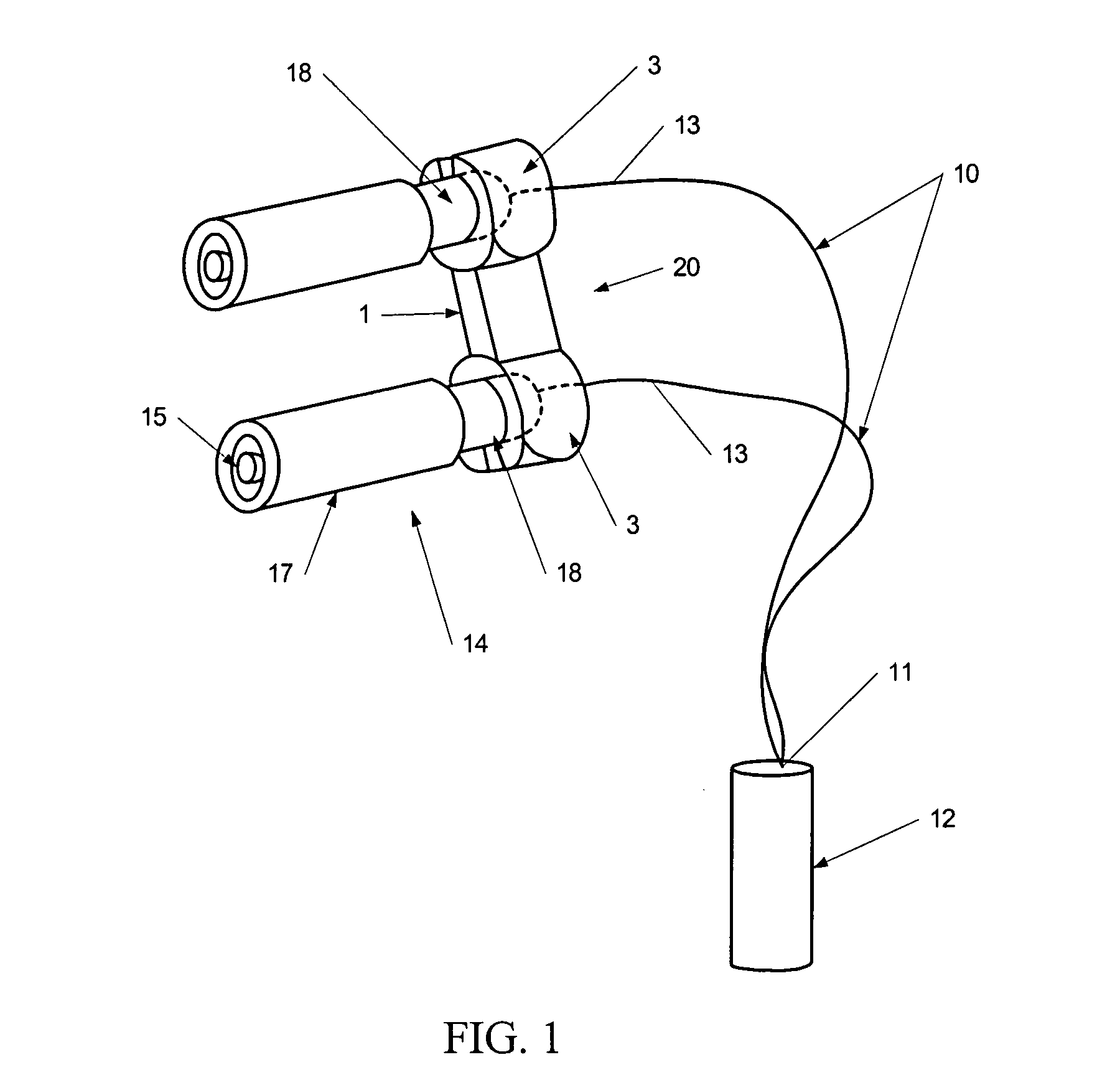
[0008]The present invention provides an extension cable system for connecting electrodes to any medical device such as, but not limited to, electrocardiographs, arrhythmia detectors, cardiac monitors. The extension cables of the invention, however, are especially useful for electrically connecting epicardial wire electrodes to an External Pacing Generator (EPG) to electrode wires. The system further provides a connector separator for maintaining electrode receiving connectors and wire electrodes in a fixed relationship relative to each other to avoid contact between electrically exposed regions of the electrodes, thereby reducing the risks of short circuits and harm to the patient, the medical device, or both.
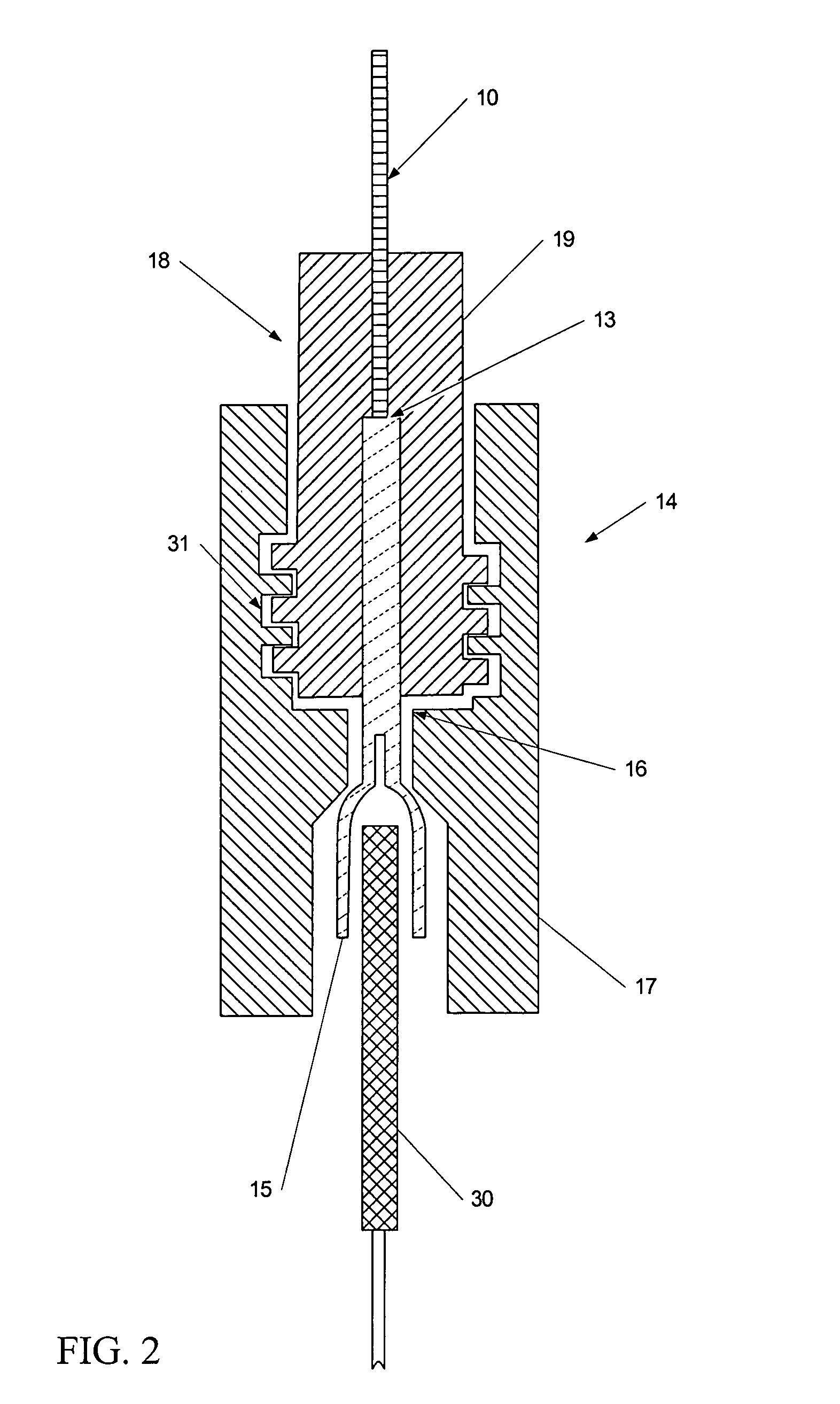
[0009]The invention provides an extension cable system comprising a pair of leads connected to a plug adapted to connect to the input socket of a medical device, dielectrically shrouded electrode receiving connector(s) connected to the leads and designed to make an electrical connection with a filamentous electrode or electrically conductive wire, and a connector separator for gripping and maintaining the electrode receiving connectors in a predetermined and rigid relationship relative to each other, thereby reducing the possibility of inadvertent contact and short circuit between non-electrically insulated regions of the inserted electrode wires. The electrode receiving connectors comprise outer shrouds that can be threadably rotated to open wire receiving chucks to receive electrode wires. The shrouds are then counter-turned to tighten the chucks against the wires.

Problems solved by technology

However, inadvertent current discharge to a patient or to attending medical personnel is sometimes possible because of exposed or uninsulated electrical connectors or plugs that electrically link the power source to the electrodes contacting the patient.
The electrodes themselves may also have uninsulated regions that can touch one another while being implanted into the patient, or due to bad positioning or being moved leading to short circuits, equipment damage and possible patient injury.
However, the insulating shrouds placed around connector pins can be incompatible with the corresponding receiving connectors that are installed in adapters located at the ends of the extension cables that connect to the current generator.
However, although the connectors themselves still remain shrouded, the pin extensions are now exposed, and reintroduce the possibility of unintended electrical contact between the pins causing a short circuit or with the patient.
These connection locking systems, however, are expensive and complex to manufacture.

Method used


Image

  • Epicardial pacer extension cable system
  • Epicardial pacer extension cable system
  • Epicardial pacer extension cable system

Examples


Embodiment Construction

[0017]A full and enabling disclosure of the present invention, including the best mode known to the inventor of carrying out the invention, is set forth more particularly in the remainder of the specification, including reference to the accompanying drawings, wherein like reference numerals designate corresponding parts throughout several figures. This description is made for the purpose of illustrating the general principles of the invention and should not be taken in the limiting sense.

[0018]The present invention provides an extension cable system suitable for electrically connecting epicardial wire electrodes to an EPG. It is contemplated, however, that the extension cable system of the present invention is also useful for connecting other external medical devices such as, but not limited to, electrocardiographs, arrhythmia detectors, cardiac monitors, and the like, to electrode wires. The system further provides a connector separator for maintaining the electrode receiving conne...


PUM


Abstract

The invention provides an extension cable system for connecting electrodes to a medical device such as an External Pacing Generator. The system further provides a connector separator for maintaining electrode receiving connectors in a fixed relationship relative to each other to avoid contact between electrically exposed regions of the electrodes. The extension cable system comprises electrically conductive leads electrically connected to a plug adapted to an electrical socket of a medical device, dielectrically shrouded electrode receiving connector(s) that form an electrical connection with a filamentous electrode or electrically conductive wire, and a connector separator for gripping and maintaining the electrode receiving connectors in a predetermined and rigid relationship relative to each other. The electrode receiving connectors comprise outer shrouds that can be threadably rotated to operate wire receiving chucks to receive electrode wires. The connector separator comprises a bridge having opposing ends adapted as bifurcated grips for gripping an electrode receiving connector.

Description

CROSS REFERENCE TO RELATED APPLICATIONS[0001]This application claims the benefit of U.S. Provisional Application No. 60 / 579,332, filed Jun. 14, 2004 (Hendrixson, Disposable Pacemaker Lead System and Kit), which is hereby incorporated herein by reference in its entirety.FIELD OF THE INVENTION[0002]The present invention relates to an extension cable system for connecting electrodes to a medical device. The invention further relates to a separator for maintaining electrode receiving connectors in a fixed relationship.BACKGROUND[0003]A number of medical devices, cardiac pacemakers for example, are intended to deliver or receive an electric current to a patient. However, inadvertent current discharge to a patient or to attending medical personnel is sometimes possible because of exposed or uninsulated electrical connectors or plugs that electrically link the power source to the electrodes contacting the patient. The electrodes themselves may also have uninsulated regions that can touch o...

Claims


Application Information

Patent Timeline
Patent Type & Authority Patents(United States)
IPC IPC(8): H01R29/00
CPCA61N1/0587Y10S439/909
Inventor HENDRIXSON, PAUL
Owner REMINGTON MEDICAL
Why Eureka
Try Eureka