Device for engine-driven goods vehicle

a technology for goods and vehicles, applied in the direction of electrical control, process and machine control, instruments, etc., can solve the problems of inexperienced drivers, overloaded drive shafts, differentials and their constituent components, and increased risk of expensive damage to axles and differential components

Inactive Publication Date: 2007-10-02
VOLVO LASTVAGNAR AB
View PDF16 Cites 10 Cited by
  • Summary
  • Abstract
  • Description
  • Claims
  • Application Information

AI Technical Summary

Benefits of technology

[0009]A main advantage of device(s) configured according to the invention lies in the fact that it is possible to use the maximum applied torque permitted in the situation, and that the risk of any damage to shafts and differentials is eliminated. A further advantage for the driver relates to handling the vehicle; he or she no longer needs to pay attention to whether differential locks are activated. The driver does not need to be as careful about increasing the torque. The service life of drive pinion units and drive shafts is markedly increased.
[0011]An advantage of this configuration is that it makes it possible to control the engine torque more precisely and thereby to use the maximum permitted torque from the engine in a certain situation.

Problems solved by technology

When one or more differential locks are activated for axle or wheel differentials, there is a risk of an unequal distribution of the torque between the drive shafts in a driving wheel pair or between respective driving wheel pairs.
In the event of high positive or negative torques from the engine of the vehicle and high transmission ratios between the engine and the driving wheels (that is to say, when low gear is selected), drive shafts, differentials and their constituent components may be overloaded if the torque distribution is too unequal.
Inexperienced drivers, however, run the risk of expensive damage to axle and differential components.
Another solution is to equip these certain prone vehicles with an over-dimensioned shafts and / or differentials which can be quite expensive.

Method used


Image

  • Device for engine-driven goods vehicle
  • Device for engine-driven goods vehicle
  • Device for engine-driven goods vehicle

Examples


Embodiment Construction

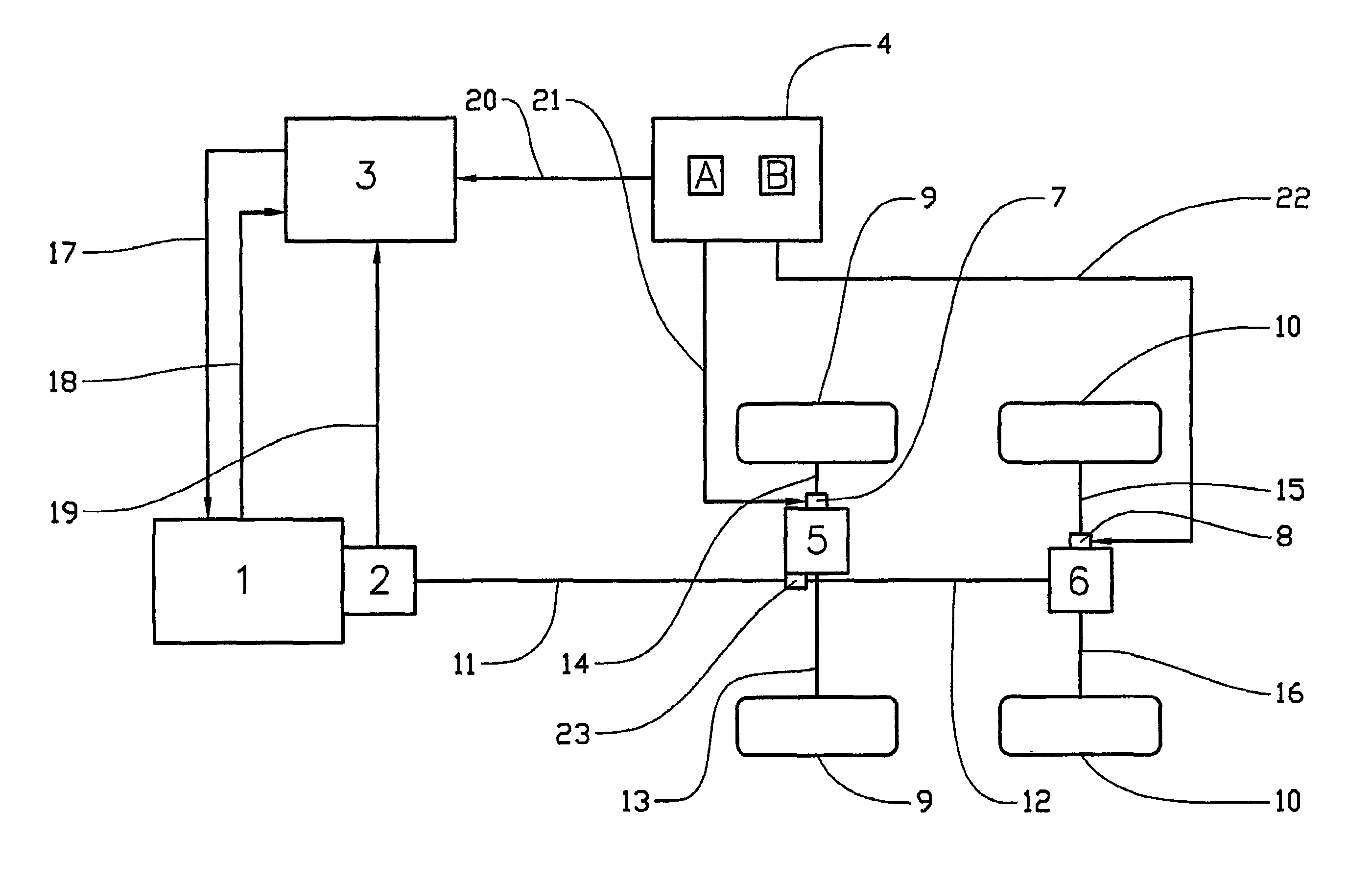
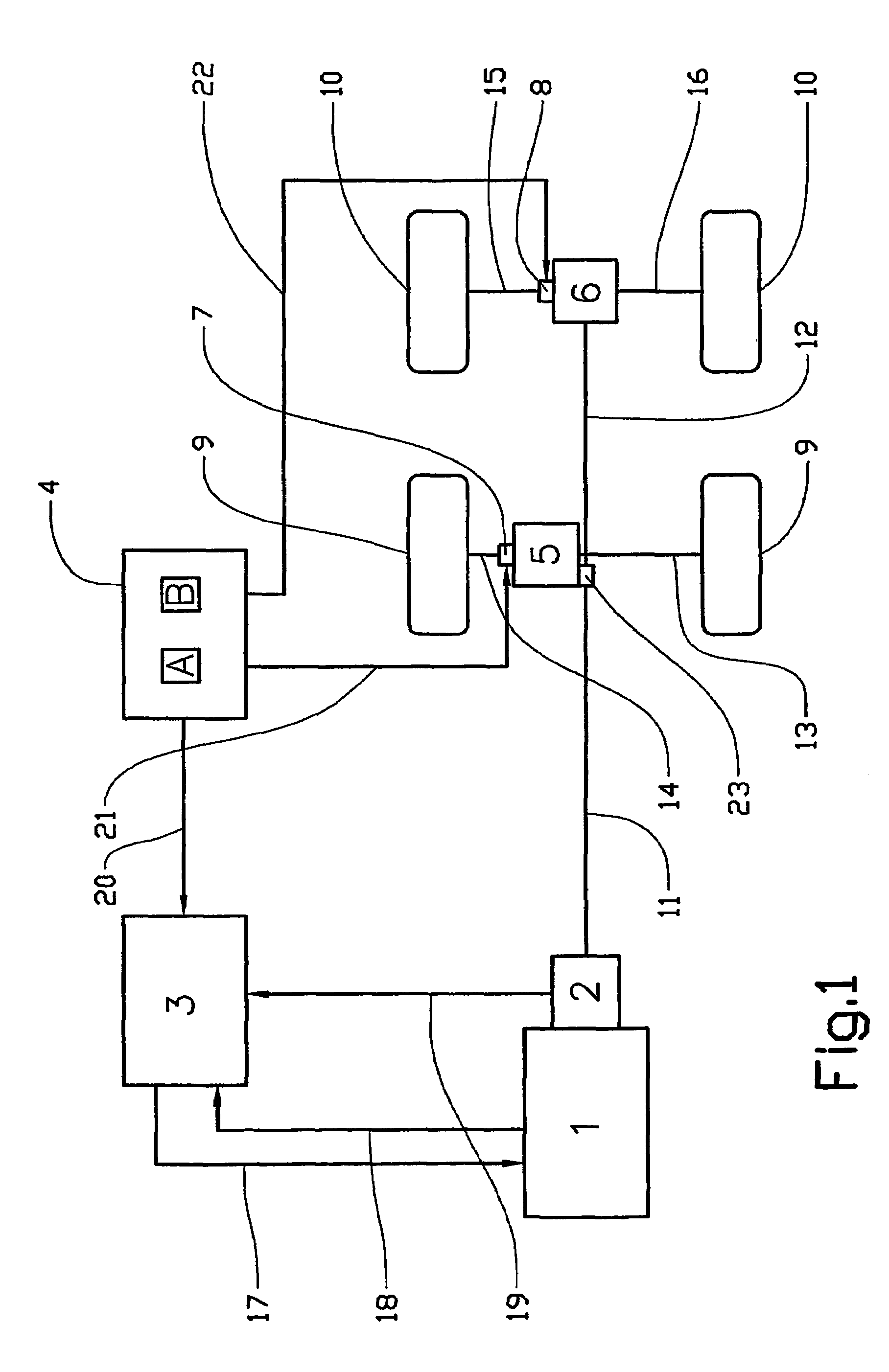
[0015]FIG. 1 shows an embodiment of the invention in which a vehicle has two driving wheel pairs 9 and 10. The driving wheels 9 are driven by an engine 1 via a gearbox 2, which is coupled to a propshaft 11, and from the propshaft 11, via a toothed gearing 23, a crown wheel (not shown) is driven in a wheel differential 5, which is in turn coupled to each of the driving wheels 9 via drive shafts 13 and 14, respectively. A differential lock 7 for blocking the differential function of the.wheel differential 5 is arranged on the drive shaft 14.

[0016]The driving wheels 10 are also driven by the engine 1 via the gearbox 2 and the propshaft 11. However, a second wheel differential 6 is instead driven via a shaft 12, which is an extension of the propshaft 11. The shaft 12 drives a crown wheel (not shown) in the second wheel differential 6, which is in turn coupled to each of the driving wheels 10 via drive shafts 15 and 16 respectively. A second differential lock 8 for blocking the different...


PUM


Abstract

Method and device for providing, in an engine-driven goods vehicle, at least two driving wheels (9, 10, 51, 52) and at least one differential (5, 6, 45, 46, 47) arranged between the driving wheels (9, 10, 51, 52). The device includes an engine control unit (3), at least one differential lock (7, 8, 48, 49, 50) for locking or braking the differential (5, 6, 45, 46, 47), the differential lock (7, 8, 48, 49, 50) being arranged between the driving wheels (9, 10, 51, 52). An operating element (4, 44) for activating each of the differential locks (7, 8, 48, 49, 50). The engine control unit (3) being configured to read-off the position of the operating element (4, 44) and to limit positive or negative output torques of the engine (1) when activating at least one of the differential locks (7, 8, 48, 49, 50) and as a function of the transmission ratio prevailing in the transmission (2, 42).

Description

CROSS-REFERENCE TO RELATED APPLICATIONS:[0001]The present application is a continuation patent application of International Application No. PCT / SE03 / 00240 filed 12 Feb. 2003 which was published in English pursuant to Article 21(2) of the Patent Cooperation Treaty, and which claims priority to Swedish Application No. 0200491-9 filed 19 Feb. 2002. Said applications are expressly incorporated herein by reference in their entireties.TECHNICAL FIELD[0002]The present invention relates to a device for controlling the engine output torque in goods (cargo) vehicles equipped with differential locks.BACKGROUND ART[0003]The function of a differential in a vehicle is to adjust (accommodate) for different speeds between driven wheels, and also to maintain total motive force; that is, ensure an even (or otherwise desired) torque distribution over all driven wheels. This is necessary because when cornering in a vehicle, the outer wheels have a greater distance to travel compared to the inner wheels...

Claims


Application Information

Patent Timeline
Patent Type & Authority Patents(United States)
IPC IPC(8): B60W10/04B60W10/10G06F17/00G06F7/00B60W10/12B60W30/18F02D41/02F16D48/12
CPCB60W10/06B60W10/12B60W10/14B60W10/16B60W30/18172F02D41/022F02D41/0225F02D41/021Y10T477/679F02D2250/26Y10T477/606
Inventor STERVIK, HANS
Owner VOLVO LASTVAGNAR AB
Why Eureka
Try Eureka