Multi-stage click switch

a multi-stage click switch and click switch technology, applied in the direction of switches with three operating positions, contact surfaces, contact shape/structure, etc., can solve the problems of increased production cost, increased time and labor, and increased operation errors, so as to reduce production cost, reduce the number of component parts, and reduce the time and labor for assembling operation.

Inactive Publication Date: 2006-06-13
YAZAKI CORP
View PDF11 Cites 16 Cited by
  • Summary
  • Abstract
  • Description
  • Claims
  • Application Information

AI Technical Summary

Benefits of technology

[0015]It is therefore an object of this invention to solve the above problems, and more specifically to provide a multi-stage click switch in which the number of component parts is reduced, and a compact design can be achieved, and this click switch is inexpensive and highly reliable.
[0024]In the above construction, a click feeling is produced by the resilient force produced when the rubber contact portion itself is elastically deformed, and therefore it is not necessary to provide a click producing mechanism, comprising special parts, as used in the conventional switch.
[0025]Therefore, the number of the component parts, as well as the time and labor for the assembling operation, is reduced, so that the production cost can be reduced. And besides, it is not necessary to provide such a click producing mechanism, comprising separate members, between the operating knob and the rubber switch member, and therefore the whole of a switch unit can be formed into a compact design.
[0026]A click feeling can be easily produced in a multi-stage manner in accordance with the number of the rubber contact portions.
[0027]The operating knob is pivotally mounted on the housing, and the plurality of pressing portions are formed on and project from the reverse surface of the operating knob at pivotally-moving opposite end portions thereof. With this construction, there can be provided the multi-stage clicks witch of the pivotally-moving type which is compact and inexpensive.

Problems solved by technology

In the case of the switch thus operable in a two-stage manner, unless a click feeling, capable of detecting the operating condition of each stage, is provided, an operation error is incurred.
Therefore, the number of the component parts of the two-stage click switch 1 increases because of the component parts of the click producing mechanism 18 and the pressing members 10 and 12, so that it is encountered a problem that the time and labor, required for the assembling operation, increased, and the production cost increases.
Further, the two-stage click switch 1 makes it difficult to form the whole of the unit into a compact design (for example, a space-saving design when it is mounted on a vehicle).

Method used


Image

  • Multi-stage click switch
  • Multi-stage click switch
  • Multi-stage click switch

Examples


first embodiment

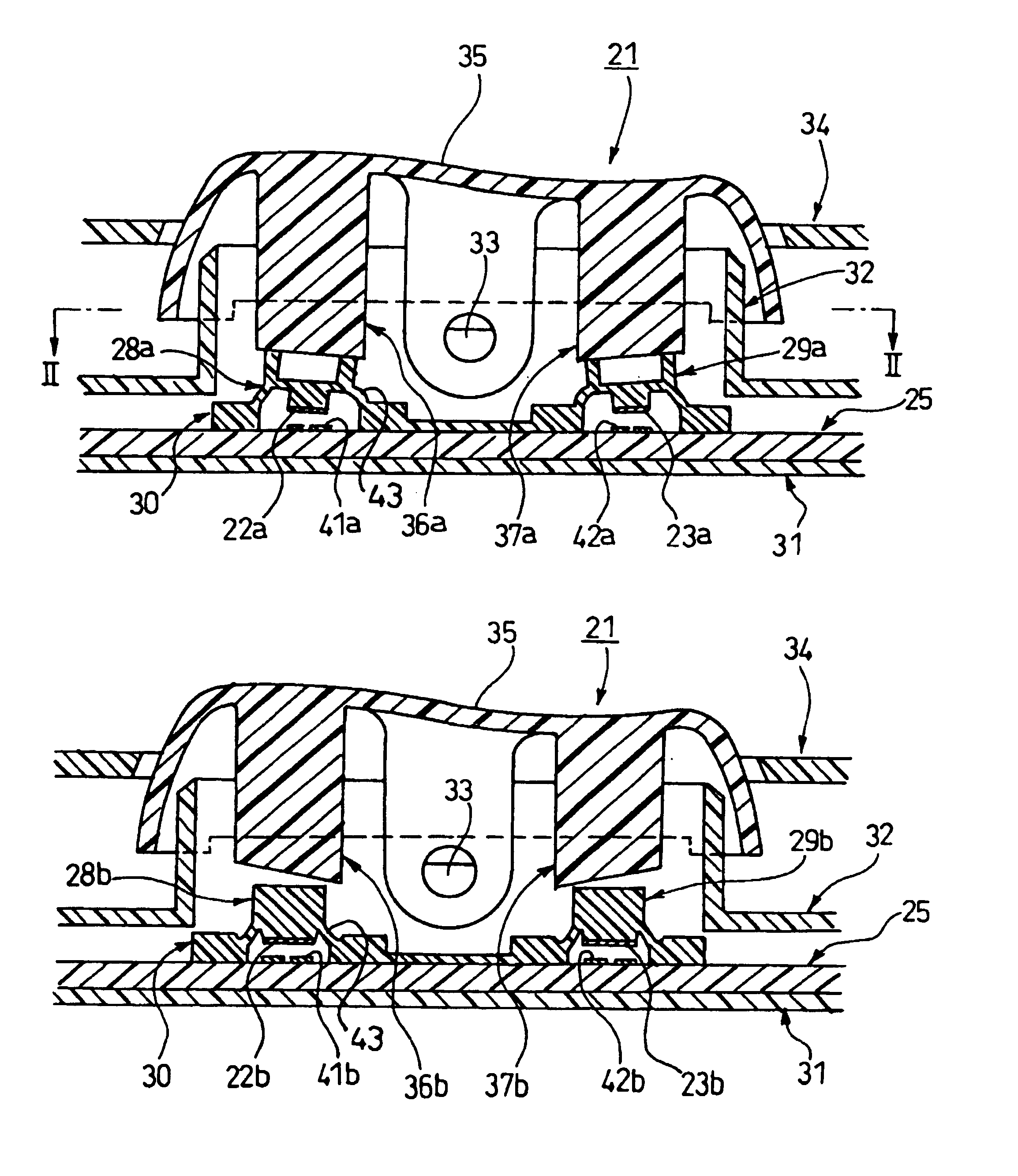
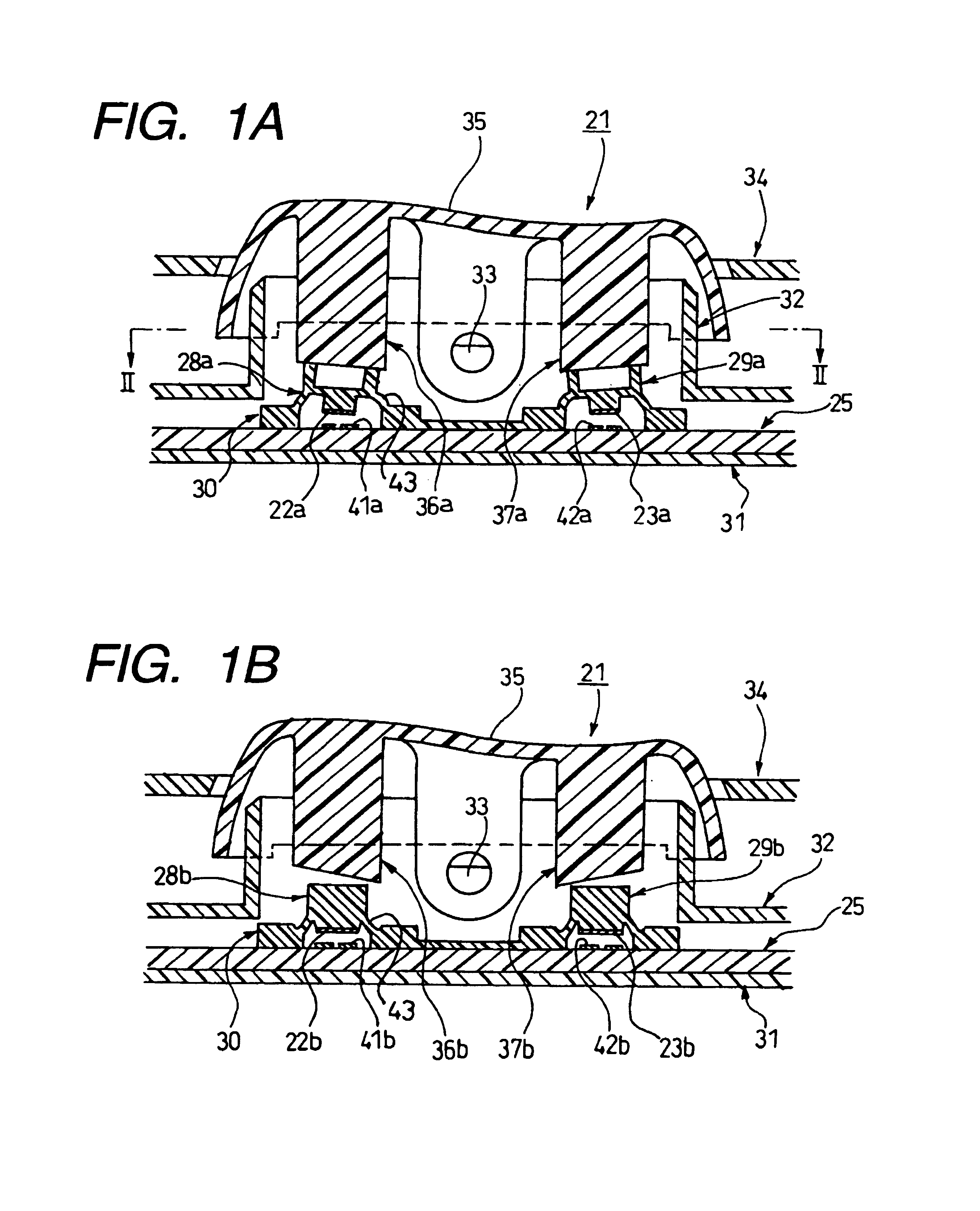
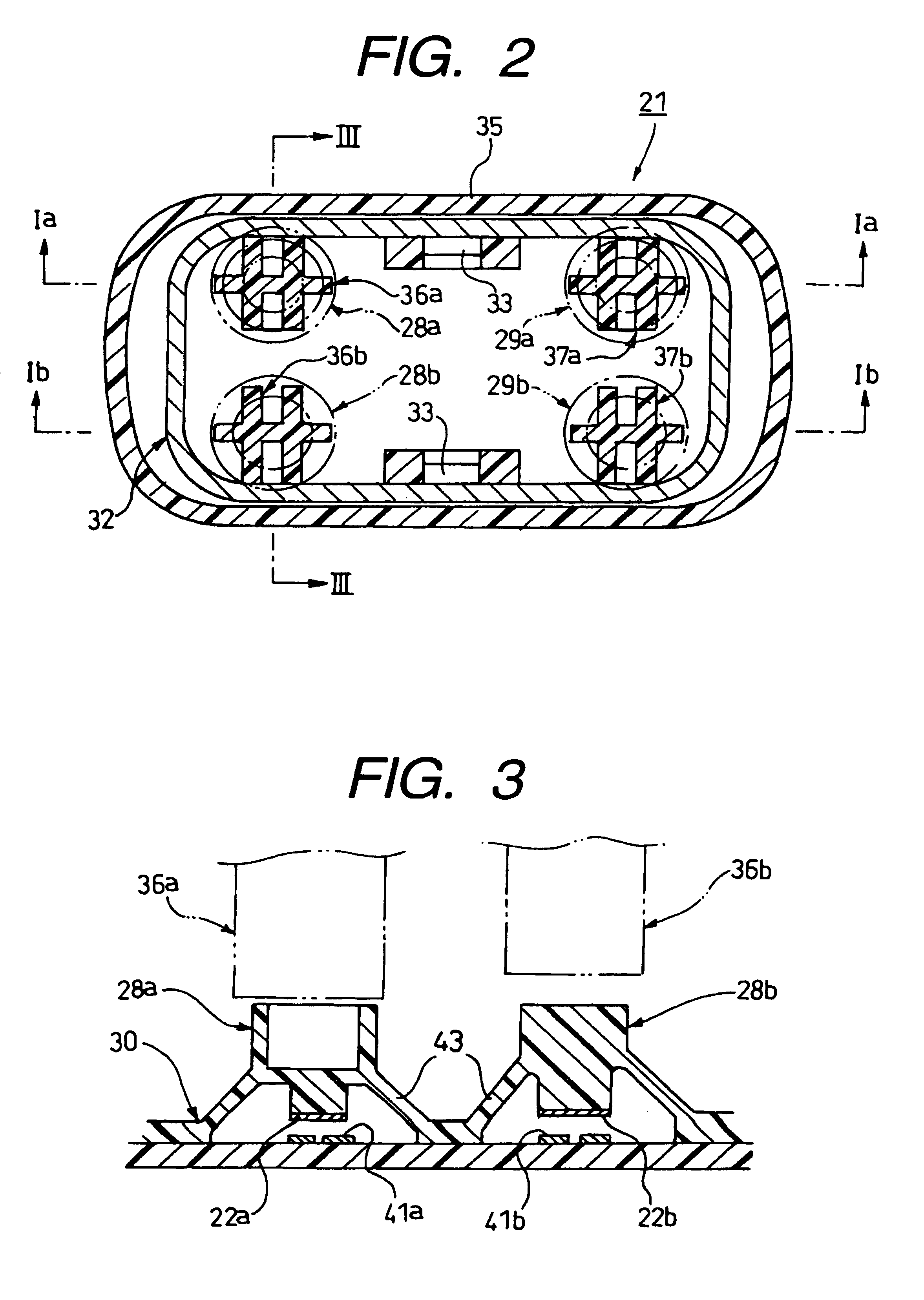
[0039]FIGS. 1A and 1B are a cross-sectional view of the multi-stage click switch according to the invention, FIG. 2 is a cross-sectional view taken along the line II—II of FIG. 1, FIG. 3 is an enlarged, cross-sectional view of an important portion, taken along the line III—III of FIG. 2, FIG. 4 is a partly-broken, perspective view of a rubber switch member shown in FIG. 3, FIGS. 5A and 5B are a cross-sectional views explanatory of an overstroke operation of a rubber contact portion shown in FIG. 3, and FIGS. 6A, 6B, 7A and 7B are cross-sectional views explanatory of the operation of the multi-stage click switch of FIG. 1.

[0040]The multi-stage click switch 21 according to this first embodiment is a pivotally-moving switch capable of achieving a two-stage click operation, and this multi-stage click switch of the pivotally-moving type can be suitably used, for example, as a switch for a power window of a vehicle.

[0041]As shown in FIGS. 1 and 2, the multi-stage click switch 21 in this f...

second embodiment

[0067]For example, a push-type multi-stage click switch 51 of the present invention, shown in FIG. 8, comprises: a pair of pressing portions 56a and 56b of different heights mounted on a reverse surface of an operating button (operating knob) 52 upwardly and downwardly-movably mounted on a housing 55; a contact circuit member 53, which has a pair of switch contact portions 59a and 59b which are disposed in opposed relation to the pressing portions 56a and 56b; a rubber switch member 54 provided between the contact circuit member 53 and the pressing portions 56a and 56b; and a pair of rubber contact portions 57a and 57b which are formed on the rubber switch member 54, and can sequentially close and open the switch contact portions 59a and 59b in a two-stage manner in accordance with the forward and backward movement of the pressing portions 56a and 56b.

[0068]A resilient force, produced when each rubber contact portion 57a, 57b is elastically deformed by the forward movement of the p...


PUM


Abstract

A multi-stage click switch (21) includes a contact circuit member (25) having switch contact portions (41a, 41b, 42a and 42b) disposed respectively in opposed relation to pressing portions (36a, 36b, 37a and 37b) formed on an operating knob (35) mounted on a housing (32), and a rubber switch member (30) having rubber contact portions (28a, 28b, 29a and 29b) which can sequentially close and open the switch contact portions in a multi-stage manner in accordance with the movement of the pressing portions. Each of the rubber contact portions produces a suitable click feeling by a resilient force, produced by elastic deformation of the rubber contact portion, at the time of operating the operating knob (35). The rubber contact portion (28a) has overstroke means by which after its conductive piece (22a, 23a) contacts the opposing switch contact portion (41a, 42a), a click feeling is not produced until the switching operation of the rubber contact portion (28b, 29b) is completed.

Description

BACKGROUND OF THE INVENTION[0001]This invention relates to an improved multi-stage click switch which produces a suitable click feeling in a multi-stage manner when operating an operation knob.[0002]As shown in FIGS. 9 and 10, one example of related switches for controlling the operation of various electric equipments (such as a power window mechanism), mounted, for example, on a door trim of a car door, is a two-stage click switch 1 which produces a suitable click feeling when pivotally operating an operating knob 11.[0003]This two-stage click switch 1 disclosed in Japanese Patent No. 2792571, comprises: a housing 2; a pair of pressing members 10 and 12 forwardly and backwardly-movably mounted on the housing 2 in spaced relation to each other; the operating knob 11 for moving the pressing members 10 and 12 downward; a contact circuit member 3, which is mounted on the housing 2 in opposed relation to the pressing members 10 and 12 and the operating knob 11, and has two pairs of cont...

Claims


Application Information

Patent Timeline
Patent Type & Authority Patents(United States)
IPC IPC(8): H01H29/16H01H23/30H01H23/00
CPCH01H23/003
Inventor SERIZAWA, YASUYOSHIKUBOTA, MINORU
Owner YAZAKI CORP
Why Eureka
Try Eureka