

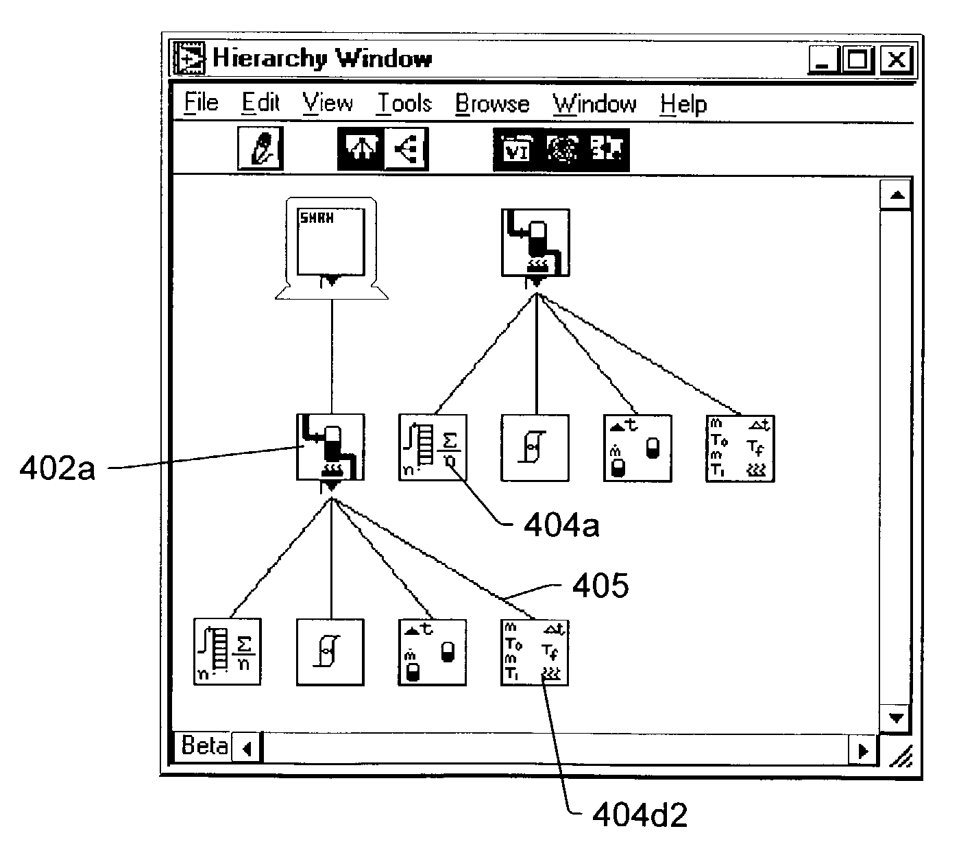
Configuration diagram which graphically displays program relationship
a configuration diagram and program technology, applied in the direction of program control, computer control, instruments, etc., can solve the problem of difficulty for users in creating various computer programs
- Summary
- Abstract
- Description
- Claims
- Application Information
AI Technical Summary
Benefits of technology
Problems solved by technology
Method used
Image

Examples
Embodiment Construction
Incorporation by Reference
[0084]The following references are hereby incorporated by reference in their entirety as though fully and completely set forth herein:
[0085]U.S. Pat. No. 4,914,568 titled “Graphical System for Modeling a Process and Associated Method,” issued on Apr. 3, 1990.
[0086]U.S. Pat. No. 5,481,741 titled “Method and Apparatus for Providing Attribute Nodes in a Graphical Data Flow Environment”.
[0087]U.S. Pat. No. 6,173,438 titled “Embedded Graphical Programming System” filed Aug. 18, 1997.
[0088]U.S. Pat. No. 6,219,628 titled “System and Method for Configuring an Instrument to Perform Measurement Functions Utilizing Conversion of Graphical Programs into Hardware Implementations,” filed Aug. 18, 1997.
[0089]U.S. patent application Ser. No. 09 / 617,600 titled “Graphical Programming System with Distributed Block Diagram Execution and Front Panel Display,” filed Jun. 13, 2000.
[0090]U.S. patent application Ser. No. 09 / 745,023 titled “System and Method for Programmatically Gen...
PUM
 Abstract
Description
Claims
Application Information