Configuration diagram with context sensitive connectivity

Active Publication Date: 2009-09-22
NATIONAL INSTRUMENTS
View PDF41 Cites 78 Cited by
  • Summary
  • Abstract
  • Description
  • Claims
  • Application Information

AI Technical Summary

Benefits of technology

[0038]Therefore, as described above, where a program icon on the configuration diagram corresponds to a graphical program, the user may perform various additional operations. As another example, if the user desires to choose a specific location in the graphical program to have a call made to a remote device, this may be performed graphically within the graphical program. In other words, if the user desires to choose a particular function node in the graphical program to make a call or invoke a program on a remote device (e.g., different computer), this may be easily performed using the block diagram of the graphical program and graphical association techniques described herein. Additionally, as described above, if the user desires to have one or more nodes or sub-programs in the graphical program execute on a remote device, this may also be performed easily using the graphical a

Problems solved by technology

As a result, in many cases it is extremely difficult for a user to be able to create vari

Method used


Image

  • Configuration diagram with context sensitive connectivity
  • Configuration diagram with context sensitive connectivity
  • Configuration diagram with context sensitive connectivity

Examples


Embodiment Construction

Incorporation by Reference

[0085]The following references are hereby incorporated by reference in their entirety as though fully and completely set forth herein:

[0086]U.S. Pat. No. 4,914,568 titled “Graphical System for Modeling a Process and Associated Method,” issued on Apr. 3, 1990.

[0087]U.S. Pat. No. 5,481,741 titled “Method and Apparatus for Providing Attribute Nodes in a Graphical Data Flow Environment”.

[0088]U.S. Pat. No. 6,173,438 titled “Embedded Graphical Programming System” filed Aug. 18, 1997.

[0089]U.S. Pat. No. 6,219,628 titled “System and Method for Configuring an Instrument to Perform Measurement Functions Utilizing Conversion of Graphical Programs into Hardware Implementations,” filed Aug. 18, 1997.

[0090]U.S. patent application Ser. No. 09 / 617,600 titled “Graphical Programming System with Distributed Block Diagram Execution and Front Panel Display,” filed Jun. 13, 2000.

[0091]U.S. patent application Ser. No. 09 / 745,023 titled “System and Method for Programmatically Gen...


PUM


Abstract

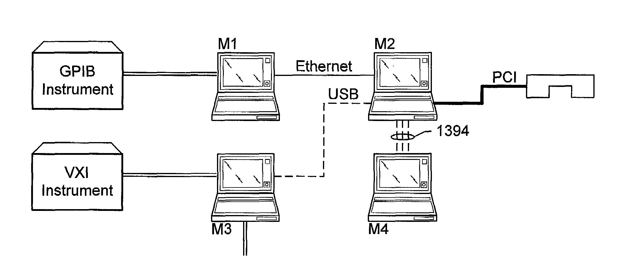
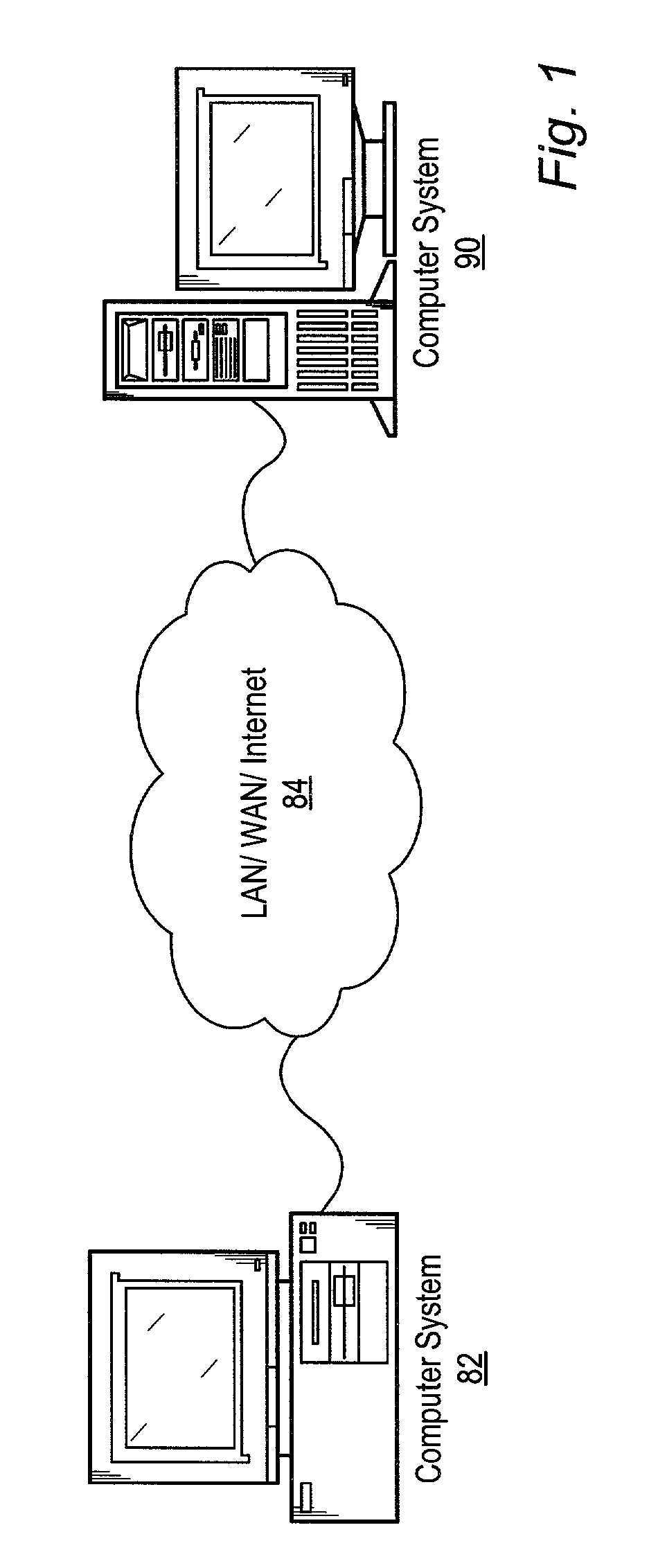
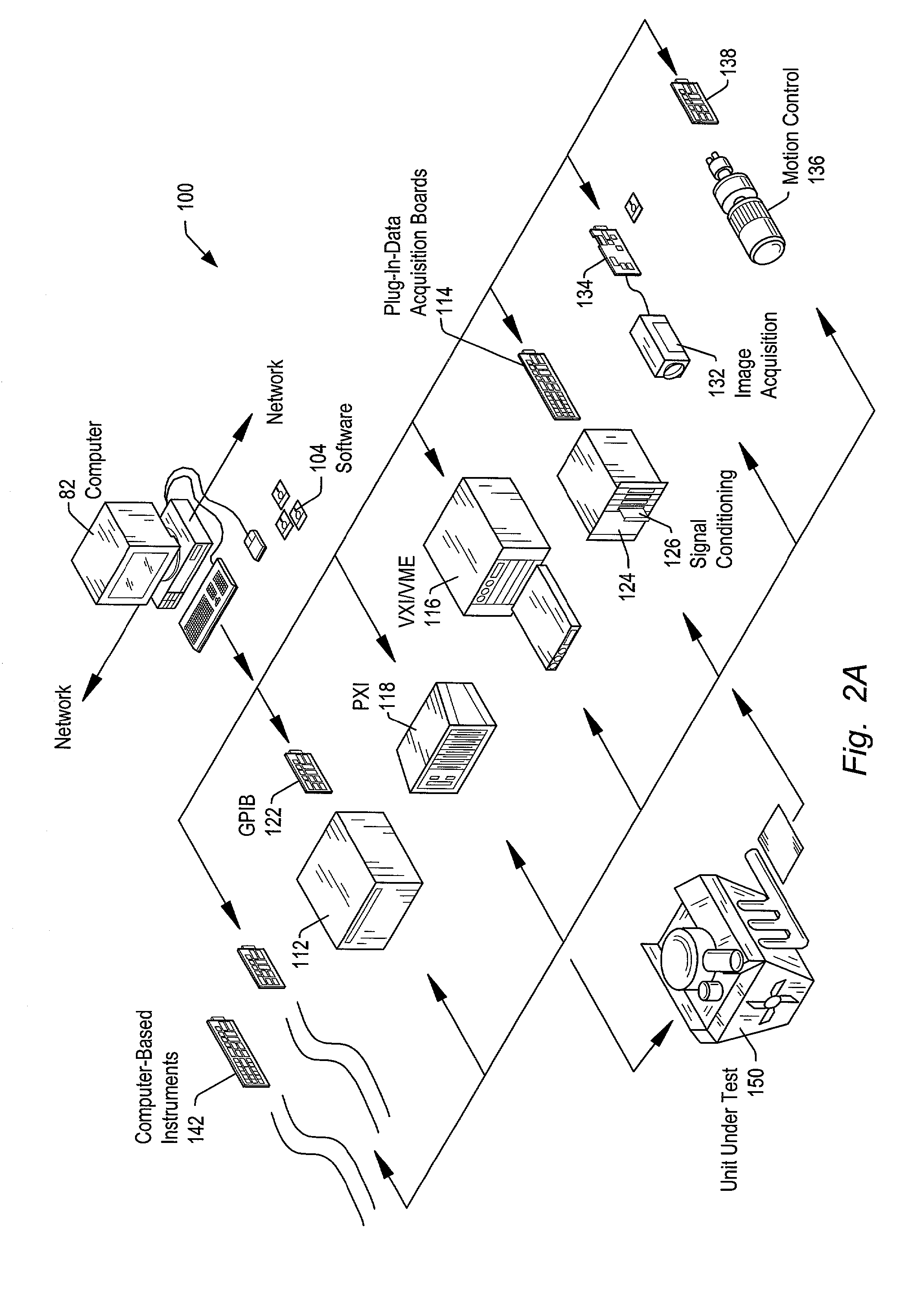
A system and method for creating and using configuration diagrams for configuring distributed systems. The methods described herein may be used for various types of operations in configuring distributed systems, including creating programs, managing programs in the distributed system, deploying programs to various distributed devices, configuring remote execution or inter-operation of distributed programs, and executing distributed applications. Embodiments of the invention utilize graphical iconic-based techniques for performing the above operations. The configuration diagram may include device icons which represent devices and program icons which represent programs. Device icons and program icons may be associated with each other to accomplish various program creation and deployment operations. Device icons and program icons may also interact with graphical program nodes or icons. Context sensitive device connections and/or program connections are displayed. An asynchronous data flow node may be used to facilitate asynchronous data flow between two graphical programs. The distributed system may also support distributed graphical debugging.

Description

PRIORITY CLAIM[0001]This application claims benefit of priority of U.S. provisional application Ser. No. 60 / 312,242 titled “System and Method for Graphically Creating, Deploying and Executing Programs in a Distributed System” filed Aug. 14, 2001, whose inventors are Jeffrey L. Kodosky, Darshan Shah and Steven W. Rogers.CONTINUATION DATA[0002]This application is a continuation-in-part of U.S. patent application Ser. No. 10 / 113,987 titled “A Configuration Diagram Which Displays a Configuration of a System” filed on Apr. 1, 2002, whose inventors are Jeffrey L. Kodosky, Darshan Shah and Steven W. Rogers, which claims benefit of priority of U.S. provisional application Ser. No. 60 / 312,242 titled “System and Method for Graphically Creating, Deploying and Executing Programs in a Distributed System” filed Aug. 14, 2001, whose inventors are Jeffrey L. Kodosky, Darshan Shah and Steven W. Rogers.FIELD OF THE INVENTION[0003]The present invention relates to the fields of system design and distri...

Claims


Application Information

Patent Timeline
IPC IPC(8): G06F9/44G06F3/00G06F3/048G09G5/00
CPCG06F3/0486G06F3/04817G06F8/34
Inventor KODOSKY, JEFFREY L.SHAH, DARSHANROGERS, STEVEN W.
Owner NATIONAL INSTRUMENTS
Why Eureka
Try Eureka