Tape threading apparatus

a threading apparatus and magnetic writing technology, applied in the field of threading mechanism in the magnetic writing/reading apparatus, can solve the problems of inability to securely hold the leader pin, and difficulty in inserting the cartridge into the cartridge, etc., and achieve the effect of reliably operating

Inactive Publication Date: 2006-06-20
NEC CORP
View PDF10 Cites 10 Cited by
  • Summary
  • Abstract
  • Description
  • Claims
  • Application Information

AI Technical Summary

Benefits of technology

[0017]Therefore, it is an object of the present invention to provide a threading mechanism for use in a magnetic writing / reading apparatus to move a leader block for pulling the magnetic tape out of the tape cartridge from the tape take-up reel to the tape cartridge, wherein the motions of the leader block are stabilized and enabled to operate reliably even in a state they are not holding the tape and the leader pin is held stably to prevent the leader block from becoming worn.
[0019]The holding element may restrain rotation of the leader block when the leader block is positioned in at least a part of the intermediate positions, and the holding element may release rotation of the leader block when the leader block is positioned in the first position.
[0020]The holding element may restrain rotation of the leader block when the leader block is in the unconnected state and positioned in at least a part of the intermediate positions, the holding element may release rotation of the leader block when the leader block is positioned in the first position, and the holding element may release rotation of the leader block when the leader block is in the connected state and positioned in at least a part of the intermediate positions.

Problems solved by technology

However, if the tape comes off the leader block while it is being threaded, the leader block will turn and be made unable to be inserted into the tape cartridge, and the apparatus can no longer function as such.
For this purpose, merely providing a guide cannot stabilize the operation of the leader block, resulting in difficulty to insert it into the cartridge.
However, engagement with such simple hooked parts cannot securely hold the leader pin 50a.
First, if the tape comes off during operation, the device will lose its mechanical function, because the leader block would then be freed and its direction destabilized, making it impossible to return the leader block into the cartridge merely by moving the arm.
Second, the shape of the leader block is made complex as shown in FIG. 8, and the cost of parts will increase correspondingly, because a rotary part should be added to the arm shaft part to prevent the leader block from interfering with the cartridge when the base is loaded with the cartridge.
Third, the insecure holding of the leader pin against the leader block makes it more likely to come off the leader block, because the leader pin is supported only by the hooked parts of the leader block. Even if a structure in which springs are fitted to the leader block is used, after repeated engagement and disengagement of the leader pin, the hooked parts of the leader block may be broken, because every time the leader pin is engaged or disengaged, the leader pin and the leader block come into friction with each other and, moreover, the shape of the leader pin requires the hooked parts to be thin. As a result, repetition of the engagement and disengagement of the leader pin would make it impossible to record data on the magnetic tape, because the wear due to the engagement and disengagement would scrape the leader block to generate dust. Thus, dust coming between the tape and the head would create a gap, which would make recording impossible.

Method used


Image

  • Tape threading apparatus
  • Tape threading apparatus
  • Tape threading apparatus

Examples


Embodiment Construction

[0050]A preferred embodiment of the present invention will be described below with reference to accompanying drawings.

[0051][Structure]

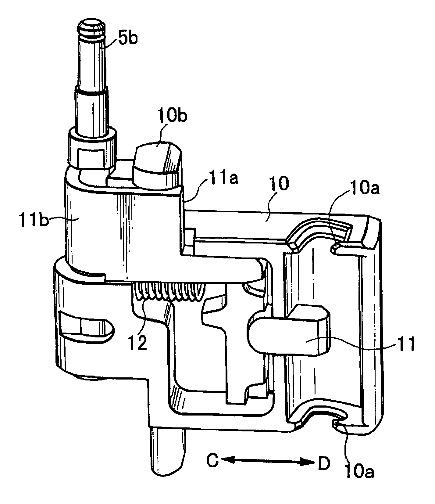
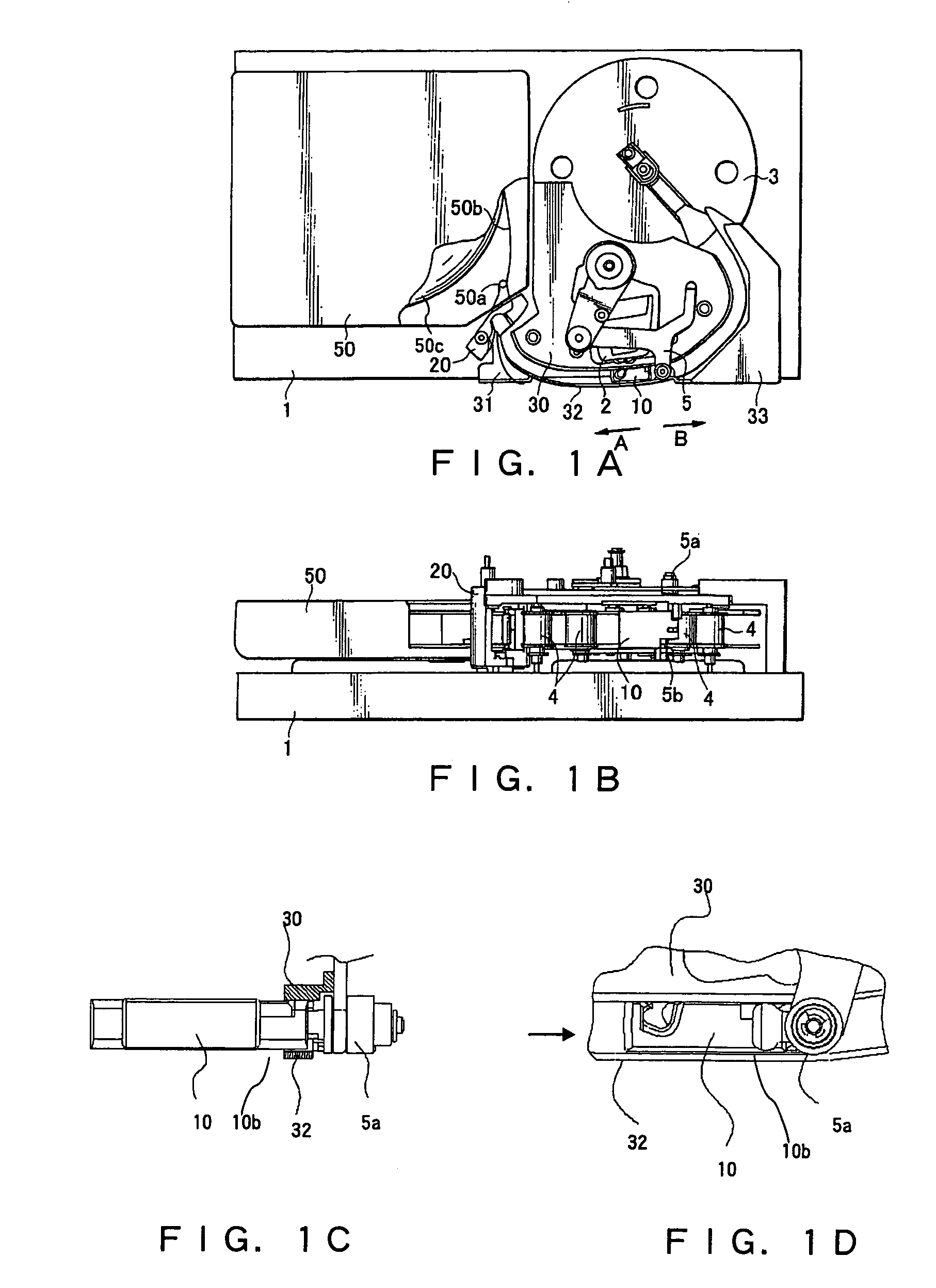
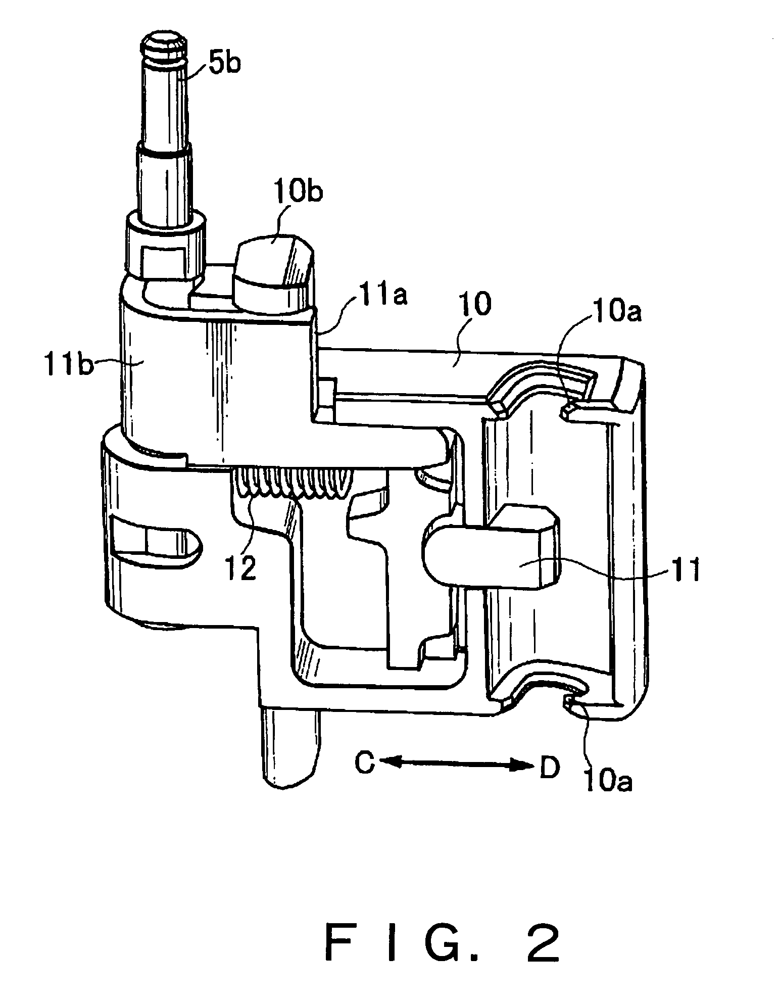
[0052]FIG. 1 consists of FIG. 1A, which shows a plan of a magnetic writing / reading apparatus according to the invention, FIG. 1B, which shows a front view of the same, FIG. 1D, which shows an enlarged view of the leader block 10 in FIG. 1A, and FIG. 1C, which shows an enlarged view of the leader block 10 in the direction of an arrow in FIG. 1D.

[0053]The tape cartridge 50 in the magnetic tape device of the magnetic writing / reading apparatus is the same as what was described in BACKGROUND OF THE INVENTION and illustrated in FIG. 6. The tape cartridge 50 has a reel 50c for winding a tape 50b.

[0054]The magnetic tape device of the magnetic writing / reading apparatus has a base 1 on which the tape cartridge 50 is loaded, a head 2 for reading and writing information out of and onto a magnetic tape, a reel 3 for taking up a tape 50b, a tape guide 4 for guidi...


PUM

PropertyMeasurementUnit
magneticaaaaaaaaaa
forceaaaaaaaaaa
structureaaaaaaaaaa

Abstract

A threading mechanism in a magnetic writing / reading apparatus wherein a leader block for taking a magnetic tape out of a tape cartridge is stabilized in motion and ensured to operate reliably even in a state of not holding the tape is to be provided. In the mechanism for threading the magnetic tape to a reel within the apparatus, the leader block for taking out a leader pin out of the tape cartridge is rotatably fitted to the arm shaft of a movable arm, and the leader block moves along guides at the time of loading the tape cartridge.

Description

BACKGROUND OF THE INVENTION[0001]The present invention relates to a threading mechanism in a magnetic writing / reading apparatus, and more particularly to a threading mechanism in a magnetic writing / reading apparatus by which a leader pin, fitted to one end of a magnetic recording tape, is taken out of a tape cartridge, and shifted to a prescribed guide path to thread the magnetic recording tape onto a reel in the apparatus.Related Art[0002]In a conventional threading mechanism, when a tape cartridge is loaded and the magnetic tape therein is pulled out of the tape cartridge, the leader pin fitted to one end of the magnetic tape is held to a leader block by a threader drive, and the leader pin is guided to a reel by way of a guide path.[0003]In order to ensure smooth threading, the leader block should be freely rotatable relative to the arm shaft. When the tape is being pulled, the leader block is pulled by the tape toward the tape cartridge and the operation is thereby stabilized. H...

Claims


Application Information

Patent Timeline
Patent Type & Authority Patents(United States)
IPC IPC(8): G03B1/58G11B15/67
CPCG11B15/673G11B15/672
Inventor MASUDA, TAKASHI
Owner NEC CORP
Why Eureka
Try Eureka