Method and device in a coupling node for a telecommunication system

a technology of a coupling node and a communication system, applied in the field of method and device in a coupling node for a telecommunication system, to achieve the effect of effectively utilizing the internal communication resources of the node and the total processor capacity in the nod

Inactive Publication Date: 2006-06-20
TELEFON AB LM ERICSSON (PUBL)
View PDF9 Cites 42 Cited by
  • Summary
  • Abstract
  • Description
  • Claims
  • Application Information

AI Technical Summary

Benefits of technology

[0013]Thus, an overarching object of the present invention is to couple a telecommunication between different networks via at least one coupling node and thereby to utilize the processor resources of the node effectively when handling the functions.
[0017]Another object is to utilize the internal communication resources of the node effectively.
[0018]The invention has the advantage that the total processor capacity in the nodes are utilized.
[0019]Another advantage is that the code for the function in question does not have to be stored permanently in a processor. Instead, the code can be loaded into the processor when needed for a communication, and thereafter the processor can be used for other functions or other objects.
[0020]Another advantage is that the number of different types of printed board assemblies can be reduced, compared to known solutions.
[0021]Yet another advantage is that the internal communication resources of the nodes are utilized effectively.

Problems solved by technology

Another problem having been addressed is to utilize the processors in the node in a flexible manner.
Yet another problem having been addressed is also to utilize the communication resources of the node in an effective manner.

Method used


Image

  • Method and device in a coupling node for a telecommunication system
  • Method and device in a coupling node for a telecommunication system
  • Method and device in a coupling node for a telecommunication system

Examples


Embodiment Construction

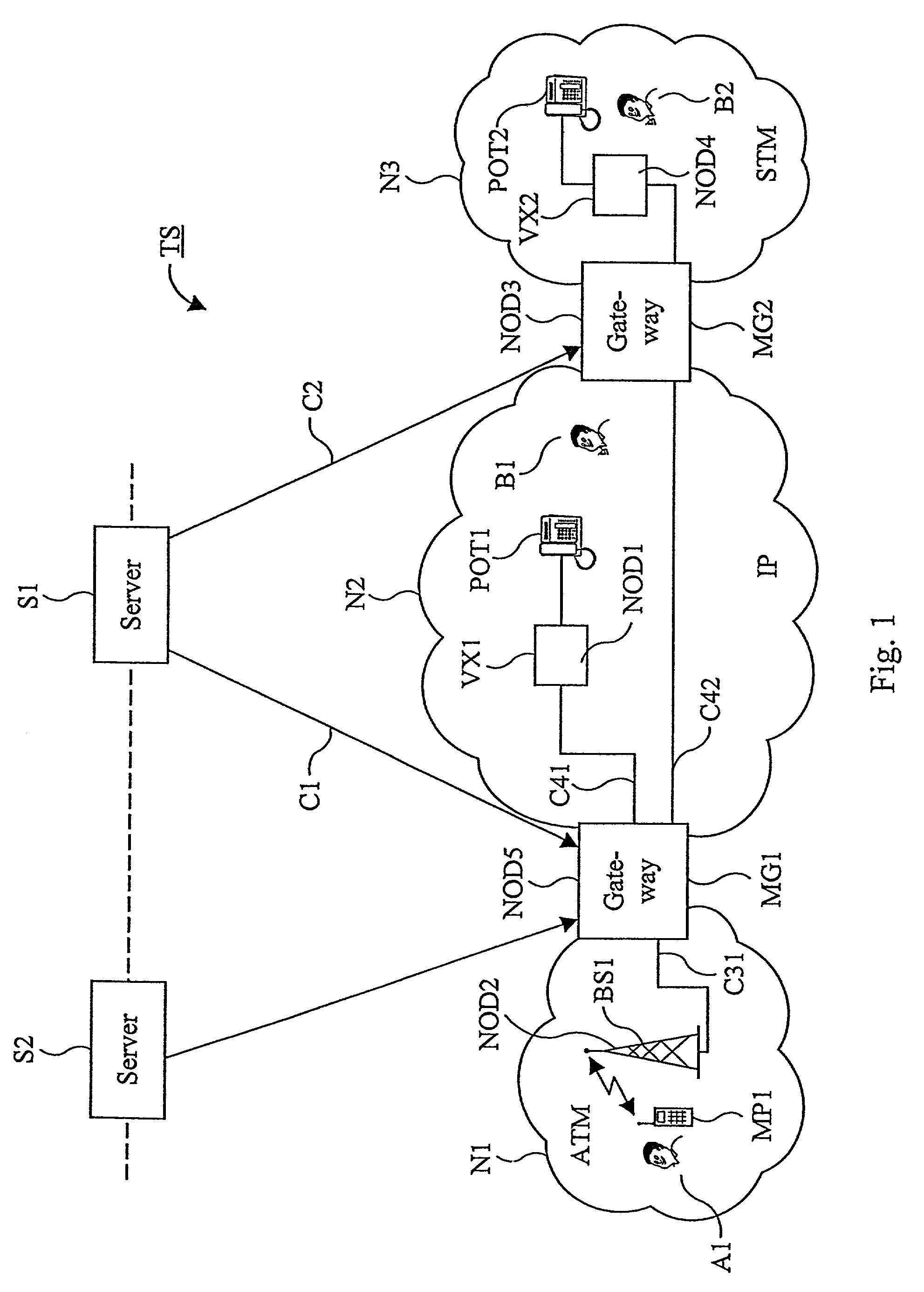
[0039]FIG. 1 shows, as an example, a view of a part of a telecommunication system TS, comprising a first network N1, being an ATM-network, a second network N2, being an IP-network, and a third network N3, being a STM-network. The term ATM here stands for Asynchronous Transfer Mode. The second network 2 is, on one hand, connected to the first network N1 through a first gateway MG1 and, on the other hand, connected to the third network N3 through a second gateway MG2. The telecommunication system also comprises a control server S1 for controlling coupling of communications. The server S1 is connected to the gateway MG1 via a connection C1 and to the gateway MG2 via a connection C2. The Figure also shows that further servers, e.g. the server S2, takes part of the telecommunication system and are in this example connected to the gateway MG1. In the network N1 there is a first subscriber A1 with a mobile terminal MP1, which can be coupled to its network through a base station BS1. The ba...


PUM


Abstract

The present invention relates to a coupling node (MG1) for coupling of communications in a telecommunication system, comprising networks (N1, N2) with different signal formats. The coupling node has switching and trunking functions (CP21, CP23) corresponding to the signal formats, and telefunctions, e.g. coders / decoders (F21) and echo cancellers (F22), which the node can couple into a communication by means of a selector (PS1). The functions are supported by printed board assemblies (CB1–CB9) in magazines (SR1), and the printed board assemblies have signal processors (DSP11–DSP13) with access points (SAP11–SAP14). The selector hunts one of the signal processors for handling one of the functions. If the processor has sufficiently free memory space in its data store and in its instruction memory and sufficient processor capacity, this processor is selected. Otherwise a new processor is hunted which is investigated in the same way.

Description

TECHNICAL FIELD[0001]The present invention relates to a device and a method for coupling, in a coupling node in a telecommunication system, a communication and thereby utilizing the processor resources of the coupling node in an effective manner.STATE OF THE ART[0002]Telecommunication systems composed by many different types of telecommunication networks have evolved. The networks can be either circuit-switched or packet-switched and can have different types of signal formats. The networks including the packet-switched ones are capable of transferring information in real time and offer in some cases a high quality on services provided, e.g. high availability, good audibility and unbroken communication. However, the networks are expensive for the operators to administrate if the requirement for high quality is to be maintained. These costs can be reduced if telecommunication networks available so far are replaced with an entirely new packet-switched network. However, this would mean ...

Claims


Application Information

Patent Timeline
Patent Type & Authority Patents(United States)
IPC IPC(8): H04L12/66H04J3/22G06F9/50H04Q3/00
CPCG06F9/5044G06F9/505H04Q3/0016H04Q2213/13106H04Q2213/13107G06F2209/509H04Q2213/13196H04Q2213/1329H04Q2213/1338H04Q2213/13389H04Q2213/13396H04Q2213/13141
Inventor PETERSEN, LARS-GORANLARSSON, GUNNARWISS, PATRIKEKSTEDT, ULF
Owner TELEFON AB LM ERICSSON (PUBL)
Why Eureka
Try Eureka