
Shower head assembly

a technology of shower head and assembly, which is applied in the direction of spraying apparatus, spraying nozzle, movable spraying apparatus, etc., can solve the problems of easy waste of water resources, and achieve the effect of reducing water flow rate and saving water

Inactive Publication Date: 2006-06-27
LU TUNG HSIEN
View PDF7 Cites 14 Cited by
  • Summary
  • Abstract
  • Description
  • Claims
  • Application Information

AI Technical Summary

Benefits of technology

[0005]The primary objective of the present invention is to provide a shower head assembly, wherein the catch cap catches the water flow and introduces the water flow through the water inlet hole into the air chamber so as to reduce the water flow rate, thereby achieving the purpose of saving water.
[0008]A further objective of the present invention is to provide a shower head assembly, wherein the water flow is ejected outward in a radiating manner by rotation of the impeller, thereby providing a massaging effect to the user.

Problems solved by technology

However, the water is directly injected outward from the water outlet holes of the water outlet panel, so that the conventional shower head has a greater water flow rate, thereby easily wasting the water resource.

Method used


Image

  • Shower head assembly
  • Shower head assembly
  • Shower head assembly

Examples


Embodiment Construction

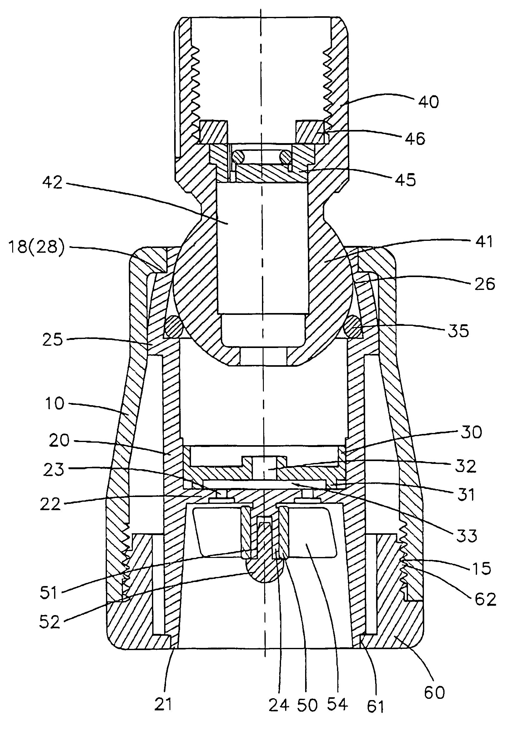
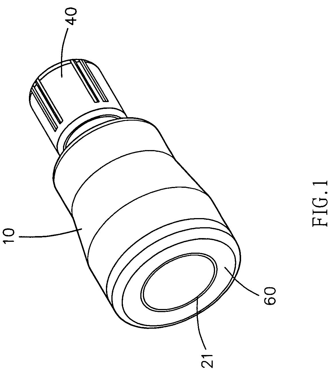
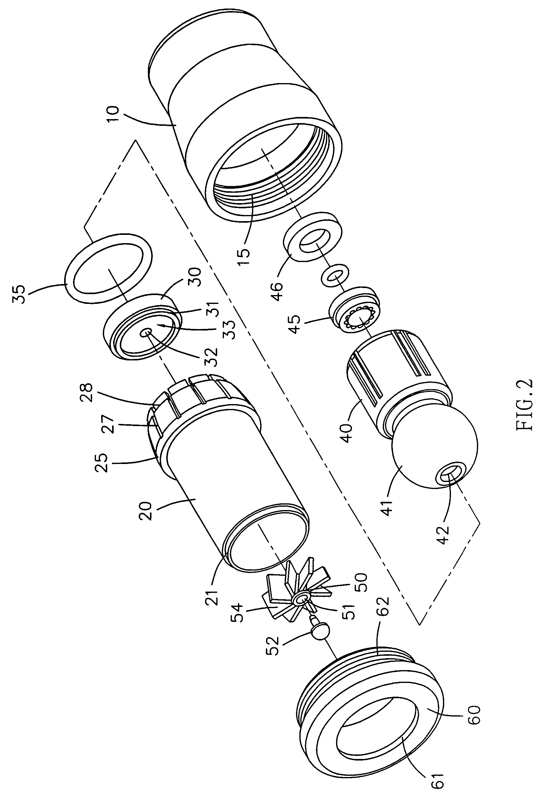
[0021]Referring to the drawings and initially to FIGS. 1–5, a shower head assembly in accordance with the preferred embodiment of the present invention comprises an outer housing 10, an inner housing 20 mounted in the outer housing 10 and having a mediate portion formed with a separation wall 22 formed with a plurality of ejection holes 23, a catch cap 30 rested on a first side of the separation wall 22 of the inner housing 20 and having an inside formed with air chamber 33 communicating with the ejection holes 23 of the separation wall 22 of the inner housing 20 and a central portion formed with a water inlet hole 32 communicating with the air chamber 33 and an inside of the inner housing 20, and an impeller 50 rotatably mounted on a second side of the separation wall 22 of the inner housing 20 and having a plurality of blades 54 aligning with the ejection holes 23 of the separation wall 22 of the inner housing 20.

[0022]The outer housing 10 has a first end formed with an annular st...


PUM


Abstract

A shower head assembly includes an outer housing, an inner housing, a catch cap, and an impeller. Thus, the catch cap catches the water flow and introduces the water flow through the water inlet hole into the air chamber so as to reduce the water flow rate, thereby achieving the purpose of saving water. In addition, the water flow is ejected outward in a radiating manner by rotation of the impeller, thereby providing a massaging effect to the user.

Description

BACKGROUND OF THE INVENTION[0001]1. Field of the Invention[0002]The present invention relates to a shower head assembly, and more particularly to a shower head assembly that saves the water resource.[0003]2. Description of the Related Art[0004]A conventional shower head comprises a universal connector attached to a wall and connected to a water pipe, a main body having a first end mounted on the universal connector, and a water outlet panel mounted on a second end of the main body and formed with a plurality of water outlet holes. When in use, the water flow from the water pipe flows through the universal connector, the main body and the water outlet panel and is injected outward from the water outlet holes of the water outlet panel. However, the water is directly injected outward from the water outlet holes of the water outlet panel, so that the conventional shower head has a greater water flow rate, thereby easily wasting the water resource.SUMMARY OF THE INVENTION[0005]The primar...

Claims


Application Information

Patent Timeline
Patent Type & Authority Patents(United States)
IPC IPC(8): B05B1/34B05B1/14B05B1/16B05B1/28
CPCB05B3/0486B05B1/26
Inventor LU, TUNG HSIEN
Owner LU TUNG HSIEN
Learn More