Solid face die plate

a technology of solid face and die plate, which is applied in the field of solid face extrusion die plate, can solve the problems of affecting the quality of solid materials, so as to reduce heat transfer, cost and time saving, and the effect of quick die chang

Active Publication Date: 2013-08-20
GALA INDUSTRIES INC
View PDF13 Cites 15 Cited by
  • Summary
  • Abstract
  • Description
  • Claims
  • Application Information

AI Technical Summary

Benefits of technology

[0010]The solid face die plate is affixed to the die insert body so as to be in contact with cutter knives and the water flowing through the cutting chamber. Because it is solid, the die plate prevents water flowing through the cutting chamber from leaking behind the die plate and also ensures that molten polymer behind the die plate cannot leak into the cutting chamber.
[0018]Yet another object of the present invention is to provide a solid face die plate for an underwater pelletizer which will conform to conventional forms of manufacture, be of simple construction and easy to use so as to provide a device that will be economically feasible, long lasting and relatively trouble free in operation.

Problems solved by technology

The insulation material is subjected to substantial degradation due to the temperatures encountered in the recess and, in some instances, does not effectively insulate the central recess area of the die face.
Ineffective insulation can result in excessive cooling of the molten polymer as it is being extruded through the extrusion orifices causing freeze off of the molten polymer at the die face.
Hence, it is easy to damage the die face when installing or removing the GEP during routine maintenance.
This is a problem in that the GEP is relatively expensive to manufacture and yet, to work correctly, must have a tight fit within the die plate.

Method used


Image

  • Solid face die plate
  • Solid face die plate
  • Solid face die plate

Examples


Embodiment Construction

[0026]In describing a preferred embodiment of the invention illustrated in the drawings, specific terminology will be resorted to for the sake of clarity. However, the invention is not intended to be limited to the specific terms so selected, and it is to be understood that each specific term includes all technical equivalents which operate in a similar manner to accomplish a similar purpose.

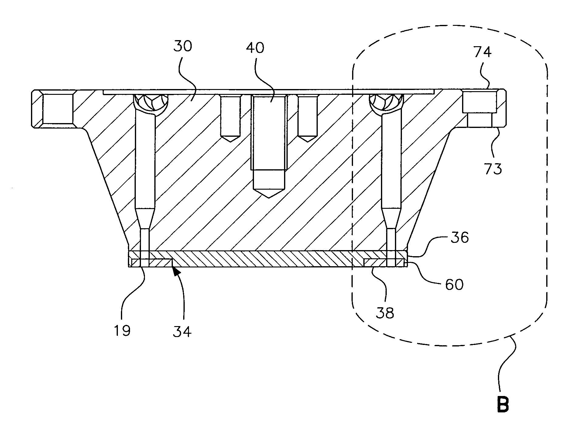
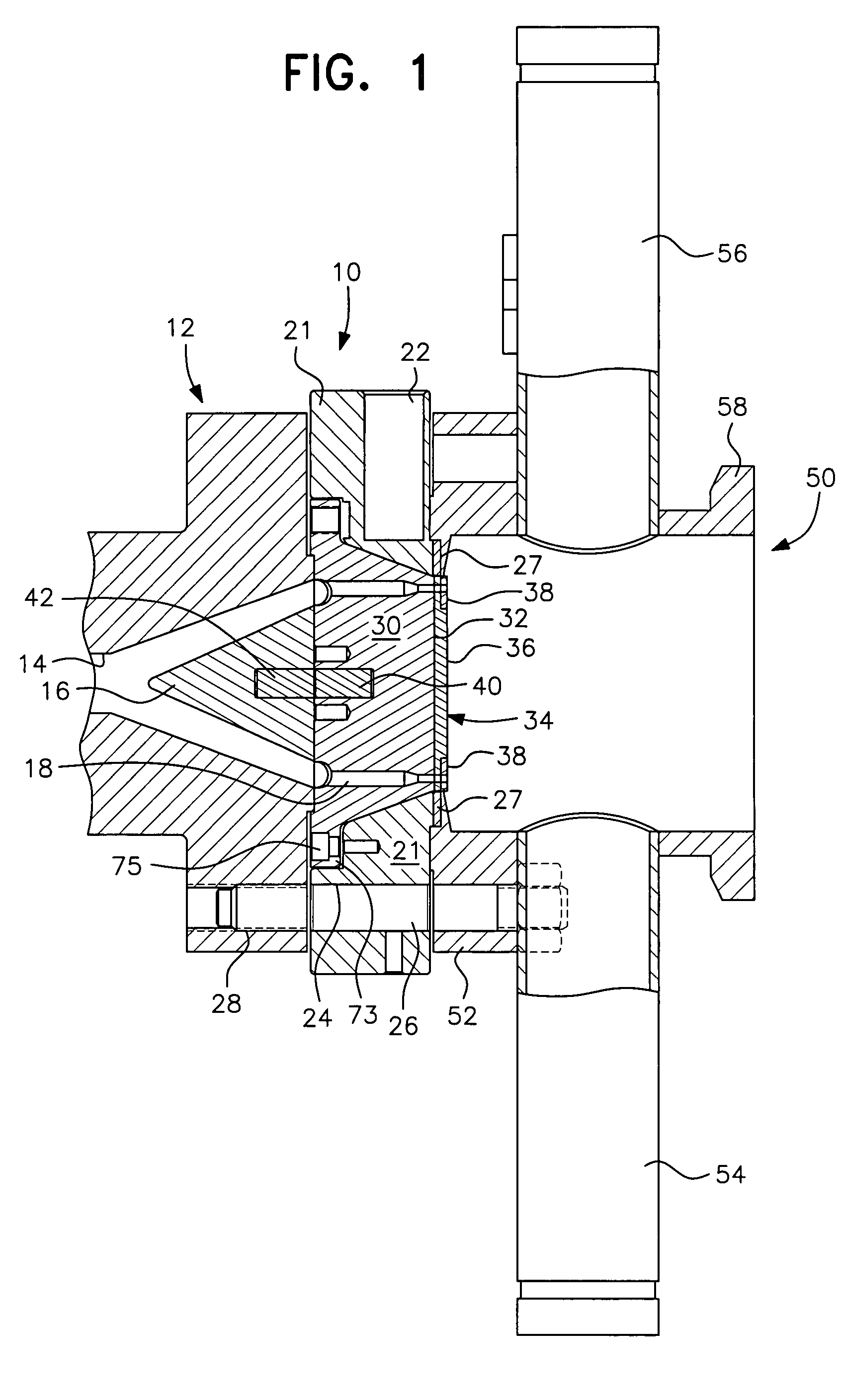
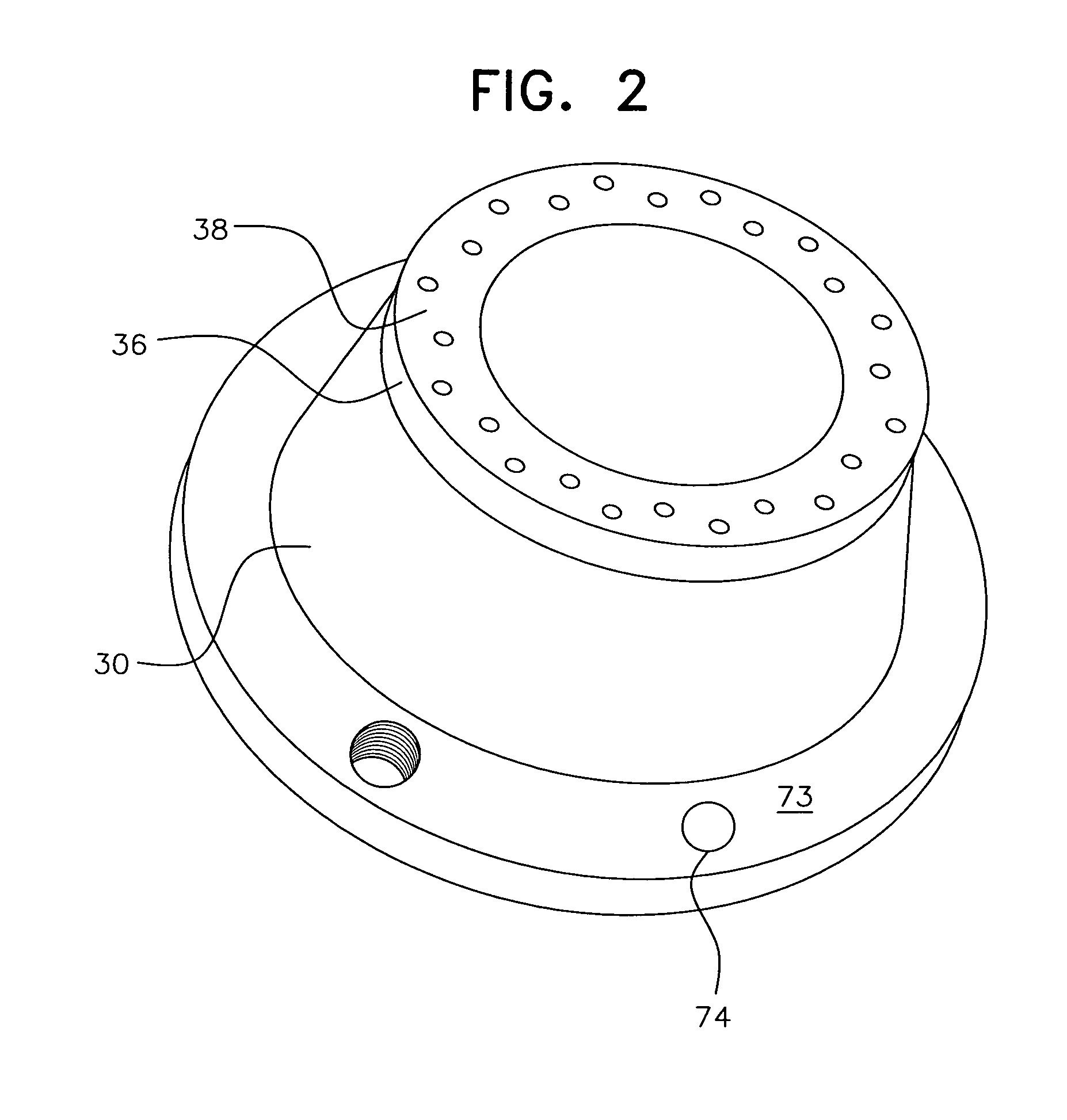
[0027]FIG. 1 of the drawings illustrates an underwater pelletizer including a solid face die plate in accordance with the present invention, generally designated by reference numeral 10, mounted on a housing, generally designated by reference numeral 12, of an extruder. The housing 12 includes an inlet passageway 14 receiving molten polymer from upstream equipment. The molten polymer is diverted outwardly by a nose cone 16 and passes through a plurality of extrusion orifices 18 in the die plate 10. The die plate 10 preferably has radial heating elements 22 extending inwardly from the periphery t...


PUM

PropertyMeasurementUnit
diameteraaaaaaaaaa
perimeteraaaaaaaaaa
heataaaaaaaaaa

Abstract

A solid face die plate for an underwater pelletizer includes a carrier or holding plate having a circular slot for holding a hard anti-wear element of highly wear-resistant material through which the extrusion orifices open for extruding polymer. The solid face die plate eliminates the need for insulation or plugging material in the center of the die plate and, by embedding the hard anti-wear element within the carrier, protects the edges of the hard anti-wear element for longer wear life.

Description

[0001]This application is entitled to and hereby claims the priority of co-pending U.S. Provisional application, Ser. No. 60 / 800,030 filed May 15, 2006.BACKGROUND OF THE INVENTION[0002]1. Field of the Invention[0003]The present invention is related to the field of underwater pelletizers and, more particularly, to a solid face extrusion die plate for an underwater pelletizer.[0004]2. Description of the Related Art[0005]Known underwater pelletizers include an extrusion die or die plate having extrusion orifices extending therethrough and through which molten polymer is extruded. A cutter hub with cutter knives is oriented in rotatable facing relationship to the face of the extrusion die plate to cut the strands of polymer into pellets. A water box with a water inlet and outlet provides circulation of water to cool and solidify the strands of extruded polymer to enable the knives on the cutter hub to cut the strands into pellets. The water circulating through the water box also entrain...

Claims


Application Information

Patent Timeline
Patent Type & Authority Patents(United States)
IPC IPC(8): B29C47/08B29C48/30B29C48/31
CPCB29B9/065B29B7/826B29B7/582B29B9/06
Inventor BROUGHMAN, MATTHEW D.
Owner GALA INDUSTRIES INC
Why Eureka
Try Eureka