
Tip-tilt-piston actuator

a tip-tilt and actuator technology, applied in the field of microelectromechanical systems, can solve the problem of not being particularly suitable for intentionally directed linear motion in the direction, and achieve the effect of high vertical movement frequency respons

Active Publication Date: 2006-06-27
WSOU INVESTMENTS LLC +1
View PDF3 Cites 14 Cited by
  • Summary
  • Abstract
  • Description
  • Claims
  • Application Information

AI Technical Summary

Benefits of technology

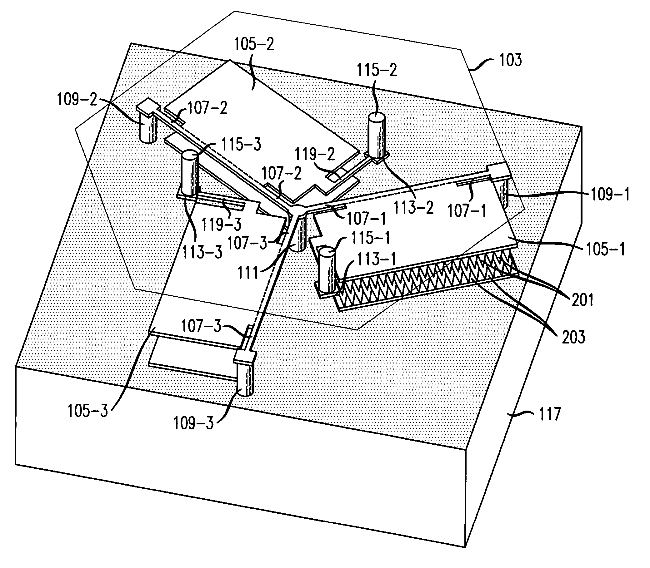
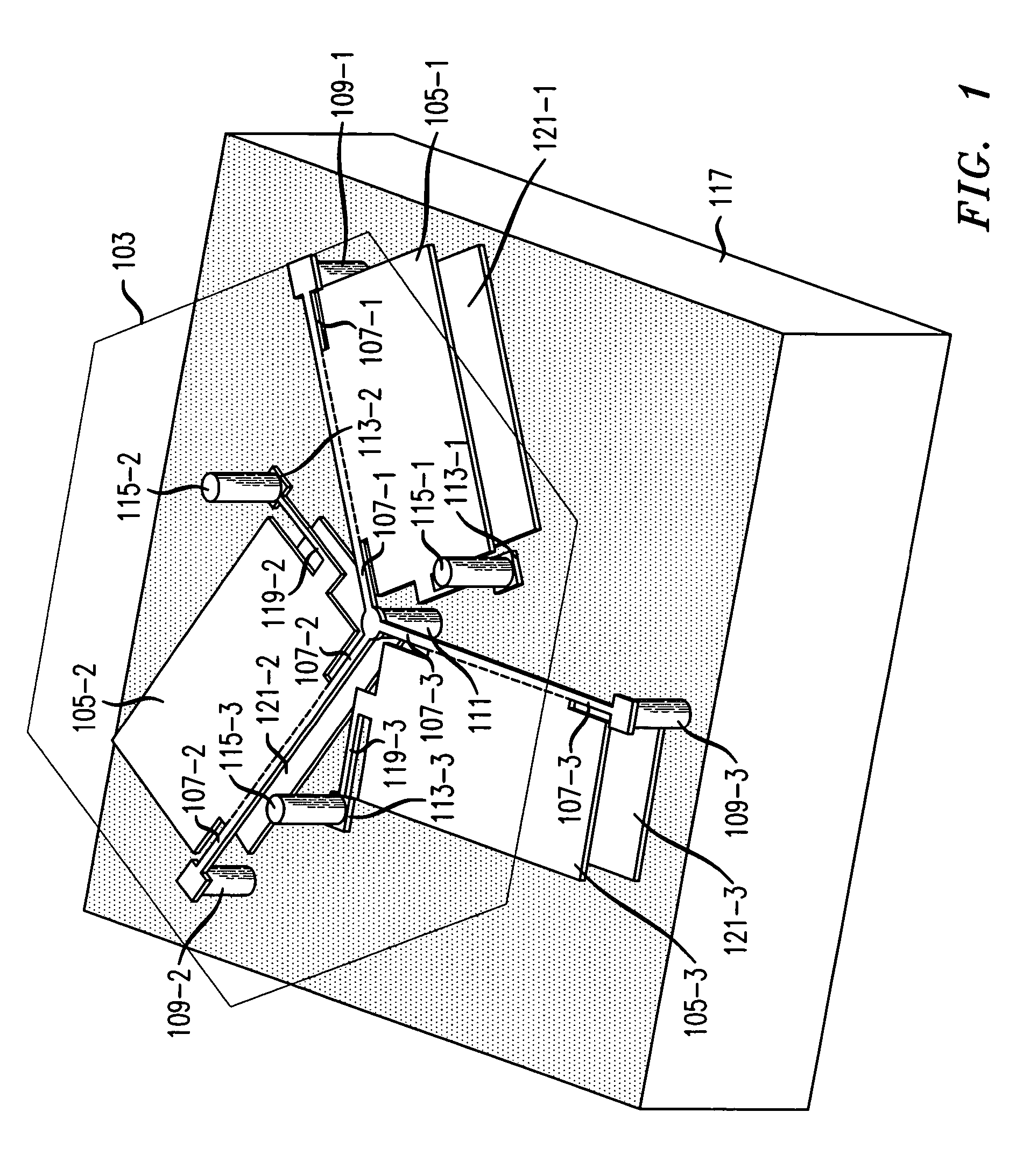
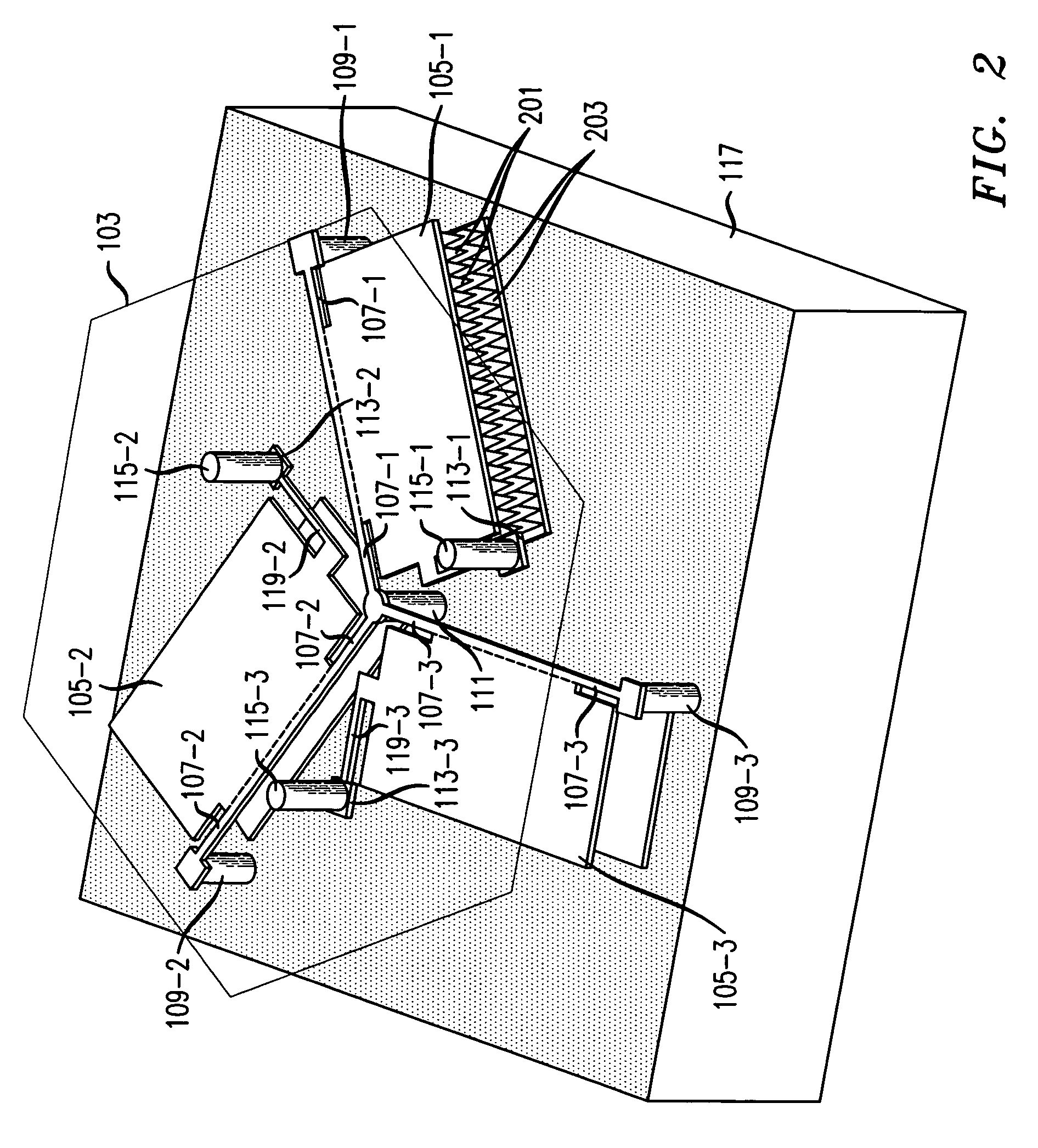
[0003]We have recognized that a freely rotatable micromechanical plate, e.g., a mirror, that is especially suitable to fast linear motion in the direction normal to the surface of the substrate from which the mirror is offset, combined with tip and tilt motion, can be achieved, in accordance with the principles of the invention, by employing at least three rotatable plates that are each suspended from a substrate via respective springs, and are coupled via other respective springs to at least three moveable plate attachment points, so that rotation of the rotatable plates about an axis transfers motion to the moveable plate attachment points. Respective posts couple the movement of each respective moveable plate attachment point to a moveable plate. In operation, the rotatable plates may be individually rotated, and the resulting motion of each rotatable plate is passed to its respective moveable plate attachment point. The combined motion of the moveable plate attachment points is passed to the moveable plate via the posts. Using proper control, the plate may be made to tip, tilt and piston. Advantageously, the piston motion may achieve a high vertical movement frequency response.

Problems solved by technology

While allowing free rotation, such a design is not especially suitable to intentionally directed linear motion in the direction normal to the surface of the substrate from which the mirror is offset, i.e., piston.

Method used


Image

  • Tip-tilt-piston actuator
  • Tip-tilt-piston actuator
  • Tip-tilt-piston actuator

Examples


Embodiment Construction

[0013]The following merely illustrates the principles of the invention. It will thus be appreciated that those skilled in the art will be able to devise various arrangements that, although not explicitly described or shown herein, embody the principles of the invention and are included within its spirit and scope. Furthermore, all examples and conditional language recited herein are principally intended expressly to be only for pedagogical purposes to aid the reader in understanding the principles of the invention and the concepts contributed by the inventor(s) to furthering the art, and are to be construed as being without limitation to such specifically recited examples and conditions. Moreover, all statements herein reciting principles, aspects, and embodiments of the invention, as well as specific examples thereof, are intended to encompass both structural and functional equivalents thereof. Additionally, it is intended that such equivalents include both currently known equivale...


PUM


Abstract

A freely rotatable micromechanical plate is achieved by employing at least three rotatable plates that are each suspended from a substrate via respective springs, and are coupled via other respective springs to at least three moveable plate attachment points, so that rotation of the rotatable plates about an axis transfers motion to the moveable plate attachment points. Respective posts couple the movement of each respective moveable plate attachment point to a moveable plate. In operation, the rotatable plates may be individually rotated, and the resulting motion of each rotatable plate is passed to its respective moveable plate attachment point. The combined motion of the moveable plate attachment points is passed to the moveable plate via the posts. Using proper control, the plate may be made to tip, tilt and piston. Advantageously, the piston motion may achieve a high vertical movement frequency response.

Description

TECHNICAL FIELD[0001]This invention relates to Micro-Electro-Mechanical-Systems (MEMS), and more particularly, to plates that can controllably tip, tilt, and piston.BACKGROUND OF THE INVENTION[0002]U.S. Pat. No. 6,480,320 issued to Nasiri on Nov. 12, 2002, discloses a freely rotatable micromechanical mirror. While allowing free rotation, such a design is not especially suitable to intentionally directed linear motion in the direction normal to the surface of the substrate from which the mirror is offset, i.e., piston.SUMMARY OF THE INVENTION[0003]We have recognized that a freely rotatable micromechanical plate, e.g., a mirror, that is especially suitable to fast linear motion in the direction normal to the surface of the substrate from which the mirror is offset, combined with tip and tilt motion, can be achieved, in accordance with the principles of the invention, by employing at least three rotatable plates that are each suspended from a substrate via respective springs, and are c...

Claims


Application Information

Patent Timeline
Patent Type & Authority Patents(United States)
IPC IPC(8): G02B26/08B81B3/00H02N1/00
CPCG02B26/0841G02B26/0833
Inventor AKSYUK, VLADIMIR ANATOLYEVICHSIMON, MARIA ELINA
Owner WSOU INVESTMENTS LLC
Learn More