Teaching data generation system for vertical multi-joint robot

a multi-joint robot and data generation technology, applied in the direction of manipulators, electric programmer control, program-controlled manipulators, etc., can solve the problems of inefficiency and inability to complete the movement of the robot within the desired cycle time, and achieve the effect of shortening the operation time of the overall arm, reducing the rotation angle, and increasing the rotation angl

Active Publication Date: 2021-12-21
KEYLEX CORP
View PDF30 Cites 0 Cited by
  • Summary
  • Abstract
  • Description
  • Claims
  • Application Information

AI Technical Summary

Benefits of technology

[0004]As the teaching data as described above is generated in offline operation, the teaching data is generally created, on one hand, to prioritize storing of operation positions in a three dimensional space as teaching points for a tool attached to a distal end of an arm of the robot as well as avoidance of interference of the tool and arm with a workpiece and other equipment, etc., between the teaching points, and on the other hand, to neglect details of poses of the arm between the teaching points. In that way, the teaching data is created including a large number of unnecessary motions of the arm between the teaching points. When the teaching data is written to a controller of a robot placed in a production plant to move the robot, movements of the robot may not be finished within desired cycle time due to the unnecessary motions of the arm between the teaching points. In that case, an operator needs to assess visually the movements of the robot actually in a production site and to correct manually the unnecessary motions of the arm while repeating trial and error, in order to finish the movements of the robot within the desired cycle time. This leads to an issue of inefficiency.
[0005]The present disclosure is made in view of the foregoing and an object of the present disclosure is to provide a teaching data generation system for a vertical multi-joint robot which can reduce correction of movements of the robot by an operator in a production site to improve operation efficiency.
[0006]To achieve the object, the present disclosure is characterized by devising generation of teaching data by utilizing faster motion of joint portions of an arm on a distal end side than that of joint portions of the arm on a base end side in a vertical multi joint robot.
[0010]According to the first aspect of the present disclosure, when the tool is moved between the teaching points due to the movement of the robot based on the teaching data, only the joint portions located at the distal end side of the arm rotate as the control point A is stationary, and the joint portions located at the distal end side of the arm have substantially larger rotation angles than the joint portions located at the base end side of the arm to maintain a linear movement of the control point A as the control point A moves linearly. Accordingly, the motors with larger angular velocity out of the motors that rotate the respective joint portions of the arm have longer operation time, thereby enabling shorter operation time of the overall arm and reduced unnecessary movements of the arm between the teaching points. An operator thus performs less tasks of assessing visually the movement of the robot actually in a production site and of correcting manually the unnecessary motions of the arm while repeating trial and error, providing higher operation efficiency.
[0011]According to the second aspect of the present disclosure, when the tool is moved between the teaching points due to the movement of the robot based on the teaching data, times spent for the movements of the joint portion V of the arm with a larger angular velocity and of the joint portion W of the arm with a smaller angular velocity are averaged. Accordingly, operation times of the joint portions V, W are substantially equal, enabling the joint portions V, W to have reduced resting and free time. The arm thus performs further efficient movements, allowing further shorter operation time of the overall arm when the tool is moved between the teaching points.

Problems solved by technology

When the teaching data is written to a controller of a robot placed in a production plant to move the robot, movements of the robot may not be finished within desired cycle time due to the unnecessary motions of the arm between the teaching points.
This leads to an issue of inefficiency.

Method used


Image

  • Teaching data generation system for vertical multi-joint robot
  • Teaching data generation system for vertical multi-joint robot
  • Teaching data generation system for vertical multi-joint robot

Examples


first embodiment

of Disclosure

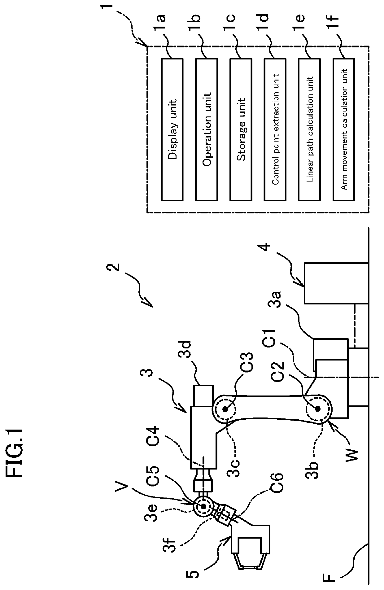
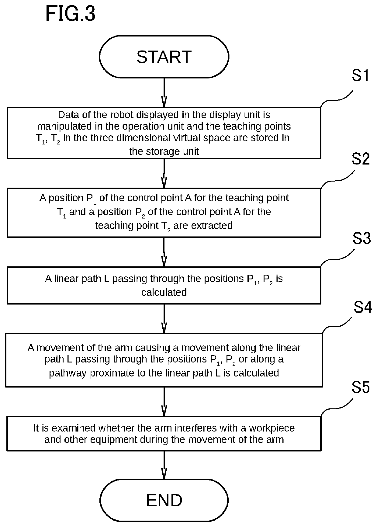
[0024]FIG. 1 illustrates a teaching data generation system 1 and a vertical multi joint robot 2 according to a first embodiment of the present disclosure. The robot 2 includes an arm 3 installed on a mount floor F and a control panel 4 coupled to the arm 3. The arm 3 has a distal end portion to which a welding gun 5 (tool) of spot welding is attached.

[0025]The arm 3 has six axes and is thus multi-jointed, in which first to sixth rotary shafts C1 to C6 are provided in turn from a mount floor F side. First to sixth drive motors 3a to 3f are mounted to respective joint portions of the first to sixth rotary shafts C1 to C6. The first to sixth drive motors 3a to 3f rotate the respective joint portions about the first to sixth rotary shafts C1 to C6.

[0026]The second drive motor 3b (arm base end side motor) mounted to a joint portion W of the second rotary shaft C2 is configured to rotate the joint portion W at an angular velocity ω1.

[0027]The fifth drive motor 3e (arm distal ...

second embodiment

of Disclosure

[0057]FIG. 10 illustrates in a simplified manner modelling data of a robot 2 configured to move based on teaching data D1 generated by using a teaching data generation system 1 according to a second embodiment of the present disclosure. The second embodiment differs from the first embodiment only in positions of teaching points T1, T2 with respect to modelling data of a workpiece 6, a process of an arm movement calculation unit 1f, and part of steps of a flow diagram, while being the same as the first embodiment in connection with other aspects. Only aspects different from the first embodiment will be explained below.

[0058]The teaching data D1 that is generated in the second embodiment is a series of movements of the robot 2 that performs welding at multiple welding positions with the robot 2 changing a pose of a welding gun 5 from one side of a workpiece 6 toward the other side, wherein the workpiece 6 is vertically symmetrical on the page of FIG. 10.

[0059]An arm movem...


PUM


Abstract

A control point extraction unit (1d) is configured to extract, when a center of a joint portion (V) of a fifth rotary shaft (C5) is defined as a control point (A), a position (P1) of the control point (A) for a teaching point (T1) and a position (P2) of the control point (A) for a teaching point (T2). A linear path calculation unit (1e) is configured to calculate a linear path (L) that passes through the position (P1) and the position (P2). An arm movement calculation unit (1f) is configured to generate teaching data (D1) by calculating a movement of an arm (3) to cause the control point (A) to move along the linear path (L) from the position (P1) to the position (P2).

Description

CROSS-REFERENCE TO RELATED APPLICATION[0001]This application is a continuation of International Application No. PCT / JP2018 / 023332 filed on Jun. 19, 2018, which is incorporated herein by reference in its entirety and for all purposes.TECHNICAL FIELD[0002]The present disclosure relates to a teaching data generation system for a vertical multi-joint robot having six axes.BACKGROUND OF THE DISCLOSURE[0003]Conventionally, in a production plant for automobiles, etc., a large number of vertical multi-joint robots perform tasks instead of human. These vertical multi-joint robots play back movements based on pre-generated teaching data. In recent years, this teaching data is first generated while a pose of a robot is assessed on a three dimensionally displayed robot as data using a workstation or computer in offline operation, and subsequently the generated teaching data is written to a controller of a robot installed in a production plant for use, as described in, for example, Japanese laid...

Claims


Application Information

Patent Timeline
Patent Type & Authority Patents(United States)
IPC IPC(8): B25J9/16B25J13/08
CPCB25J9/163B25J9/1664B25J13/088G05B19/42B25J9/046B25J9/126
Inventor FURUTA, TAKESHIABE, FUMIKA
Owner KEYLEX CORP
Why Eureka
Try Eureka