
Microphone circuits having adjustable directivity patterns for reducing loudspeaker feedback and methods of operating the same

Active Publication Date: 2006-06-27
SONY ERICSSON MOBILE COMM AB
View PDF6 Cites 14 Cited by
  • Summary
  • Abstract
  • Description
  • Claims
  • Application Information

AI Technical Summary

Benefits of technology

[0004]Some embodiments of the present invention provide a microphone circuit that includes a first microphone, a second microphone, an adjustable delay unit, and a combiner. The first microphone generates a first microphone signal that includes a contribution associated with an output signal that is generated by a loudspeaker in response to an input signal. The second microphone generates a second microphone signal that includes a contribution associated with the output signal from the loudspeaker. The delay unit adjustably delays the second microphone signal by a delay value. The combiner combines the delayed second microphone signal and the first microphone signal to provide a combined microphone signal. The delay unit adjusts the delay value so as to reduce at least a portion of the contribution to the combined microphone signal that is associated with the output signal from the loudspeaker.
[0005]According to some further embodiments of the present invention, the adjustable delay unit may adjust a directivity pattern created by the first and second microphones based on the contribution to the combined microphone signal that is associated with the output signal from the loudspeaker. Accordingly, the adjustable delay unit may steer the directivity pattern so that a direction of reduced sensitivity of the microphones may be in the direction of the output signal from the loudspeaker.
[0006]The adjustable delay unit may adjust the delay value responsive to the input signal to the loudspeaker and the combined microphone signal. The combiner may remove at least a portion of one of the first and second microphone signals from the other one of the first and second microphone signals. The adjustable delay unit may adjust the delay value so as to minimize the contribution to the combined microphone signal that is associated with the output signal from the loudspeaker. The adjustable delay unit may remove at least a portion of the input signal to the loudspeaker from the combined microphone signal to provide a difference signal, and may adjust the delay value based on the difference signal. The microphone circuit may further include an inversion unit that inverts the input signal to the loudspeaker, and a summation unit that sums the inverted input signal and the combined microphone signal to provide the difference signal. The inversion unit may alternatively invert the combined microphone signal, and the summation unit may sum the inverted combined microphone signal and the input signal to the loudspeaker to provide the difference signal.
[0007]Other embodiments of the present invention provide a method of operating a microphone circuit. A first microphone signal is generated via a first microphone and a second microphone signal is generated via a second microphone. The first and second microphone signals include contributions associated with an output signal that is generated by a loudspeaker in response to an input signal. The second microphone signal is adjustably delayed by a delay value. The delayed second microphone signal is combined with the first microphone signal to provide a combined microphone signal. The delay value is adjusted based on the input signal to the loudspeaker and the combined microphone signal so as to reduce at least a portion of the contribution to the combined microphone signal that is associated with the output signal from the loudspeaker.
[0008]According to further embodiments of the present invention, the combining may remove at least a portion of one of the first and second microphone signals from the other one of the first and second microphone signals. The delay value may be adjusted to minimize the contribution to the combined microphone signal associated with the output signal from the loudspeaker. In other embodiments, the delay value may be adjusted to adjust a directivity pattern created by the first and second microphones based on a contribution to the combined microphone signal associated with the output signal from the loudspeaker.

Problems solved by technology

However, in noisy environments and / or where long time delays may occur in the feedback of sound, some echo cancellation circuits can negatively affect the quality of the sound that is provided by the microphone and can, for example, increase echoes or introduce unwanted noise.

Method used


Image

  • Microphone circuits having adjustable directivity patterns for reducing loudspeaker feedback and methods of operating the same
  • Microphone circuits having adjustable directivity patterns for reducing loudspeaker feedback and methods of operating the same
  • Microphone circuits having adjustable directivity patterns for reducing loudspeaker feedback and methods of operating the same

Examples


Embodiment Construction

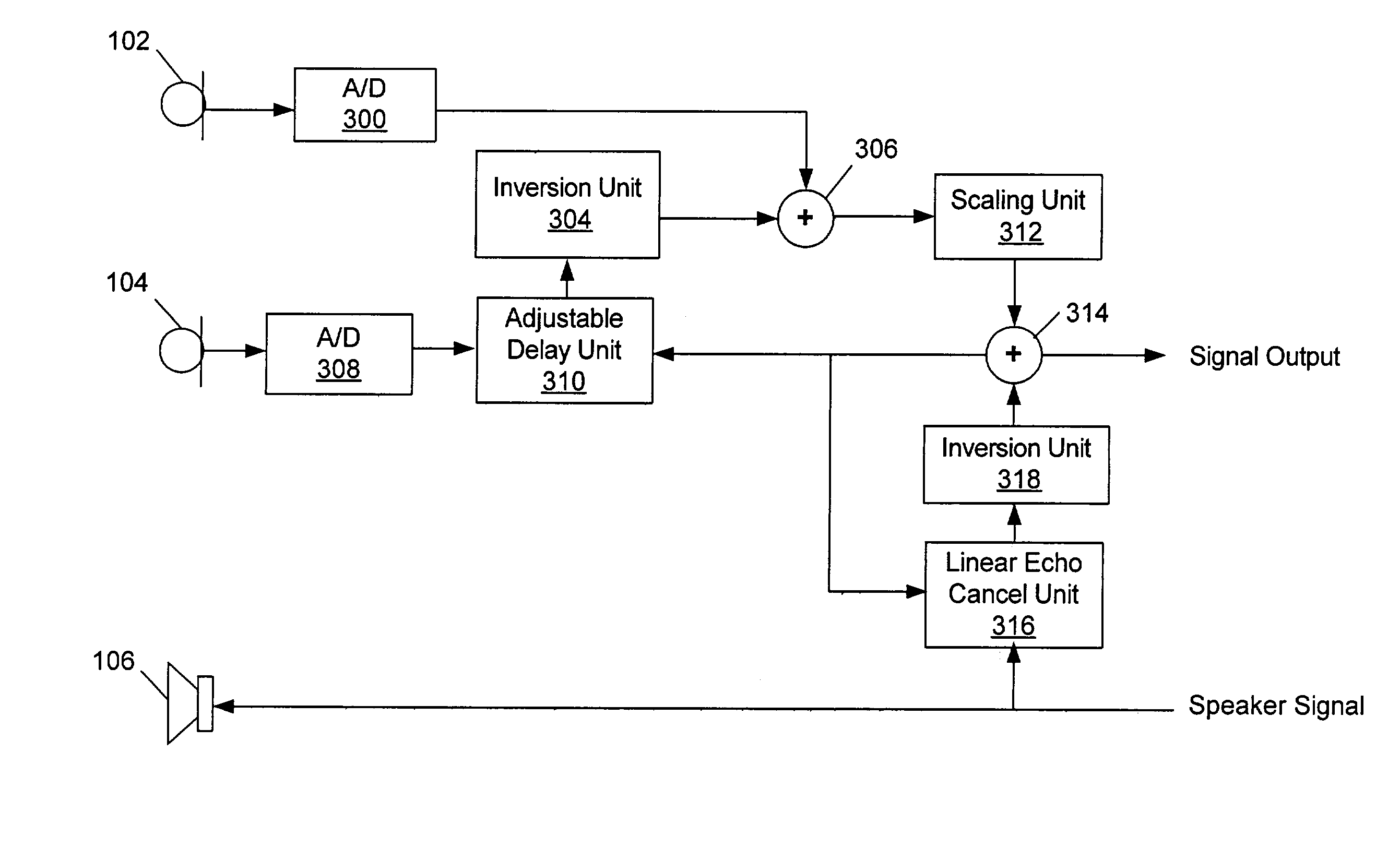
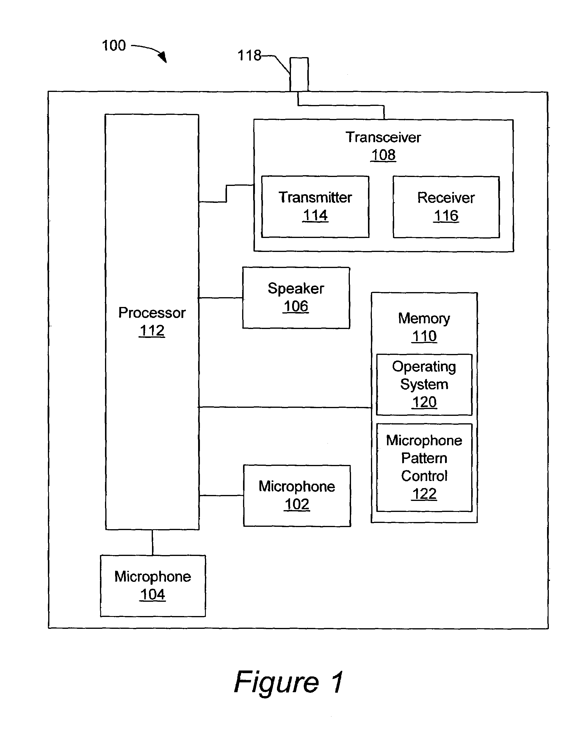
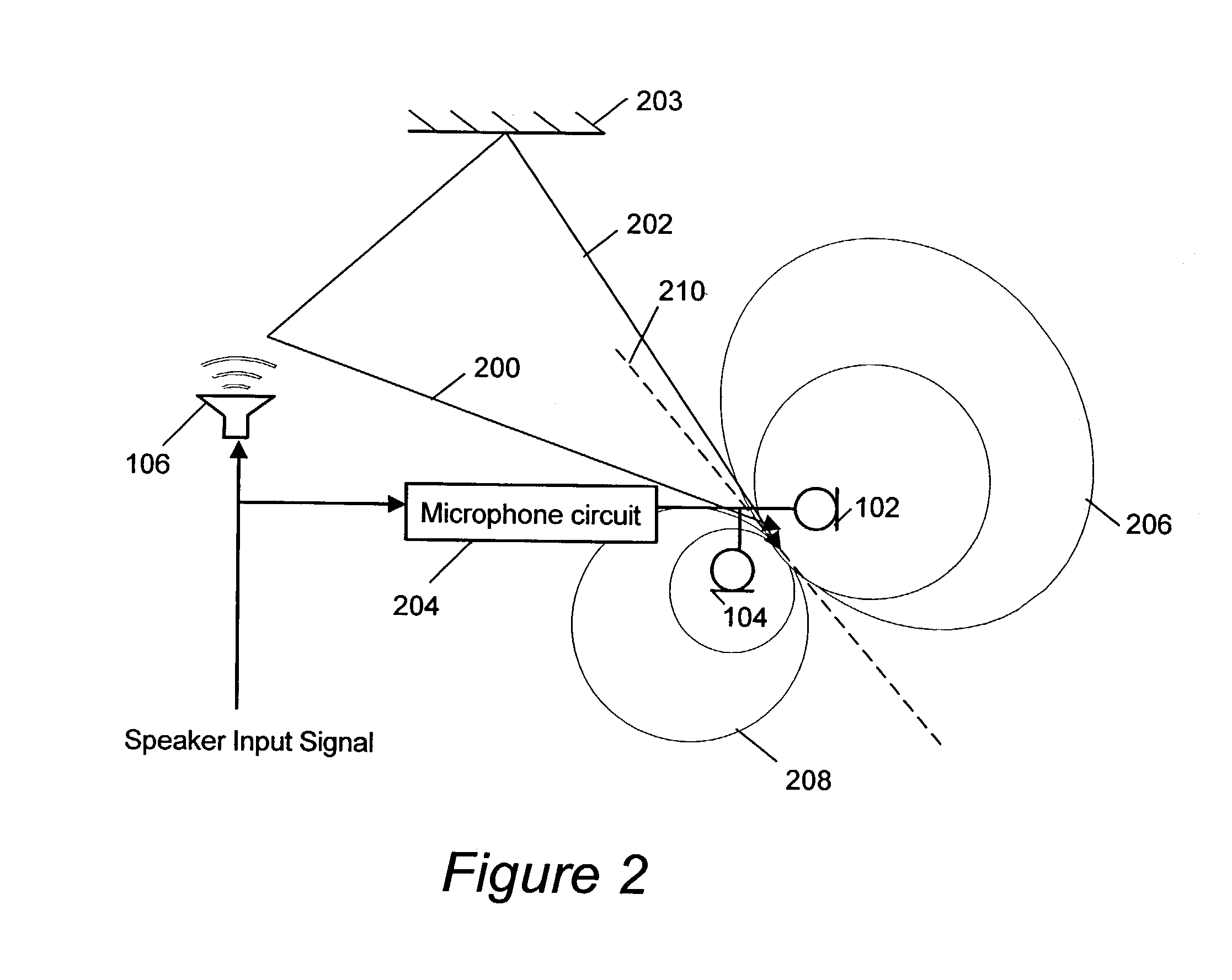
[0016]While the invention is susceptible to various modifications and alternative forms, specific embodiments thereof are shown by way of example in the drawings and will herein be described in detail. It should be understood, however, that there is no intent to limit the invention to the particular forms disclosed, but on the contrary, the invention is to cover all modifications, equivalents, and alternatives falling within the spirit and scope of the invention as defined by the claims. Like reference numbers signify like elements throughout the description of the figures. It should be further understood that the terms “comprises” and / or “comprising” when used in this specification is taken to specify the presence of stated features, integers, steps, operations, elements, and / or components, but does not preclude the presence or addition of one or more other features, integers, steps, operations, elements, components, and / or groups thereof.

[0017]The present invention may be embodied...


PUM


Abstract

A microphone circuit includes a first microphone, a second microphone, an adjustable delay unit, and a combiner. The first microphone generates a first microphone signal that includes a contribution associated with an output signal that is generated by a loudspeaker in response to an input signal. The second microphone generates a second microphone signal that includes a contribution associated with the output signal from the loudspeaker. The adjustable delay unit delays the second microphone signal relative to the first microphone signal by a delay value. The combiner combines the delayed second microphone signal and the first microphone signal to provide a combined microphone signal. The adjustable delay unit adjusts the delay value so as to reduce at least a portion of the contribution to the combined microphone signal that is associated with the output signal from the loudspeaker.

Description

BACKGROUND OF THE INVENTION[0001]The present invention relates to communication circuits that include a microphone and a loudspeaker, and, more particularly, to microphone circuits and methods for reducing loudspeaker feedback and echo.[0002]When a communication system includes a microphone and loudspeaker that are closely spaced, some sound from the loudspeaker may be sensed by the microphone and fed back through the communication system. Such feedback can create an echo effect where, for example, a user's voice is fed back to the user and heard as an echo.[0003]Echo cancellation circuits have been employed in communication systems, for example, in land-line phones, to reduce the feedback from a loudspeaker through a microphone. However, in noisy environments and / or where long time delays may occur in the feedback of sound, some echo cancellation circuits can negatively affect the quality of the sound that is provided by the microphone and can, for example, increase echoes or intro...

Claims


Application Information

Patent Timeline
IPC IPC(8): H04R3/00H04M9/08
CPCH04M9/082H04R3/005H04R25/407
Inventor ISBERG, PETERGUSTAVSSON, STEFAN
Owner SONY ERICSSON MOBILE COMM AB
Learn More