

Dynamic selection of a compression algorithm for trace data
a compression algorithm and dynamic selection technology, applied in the field of on-chip debugging, can solve the problems of longer development time, increased workload, and significant cost of developing and debugging new software products
- Summary
- Abstract
- Description
- Claims
- Application Information
AI Technical Summary
Problems solved by technology
Method used
Image

Examples
Embodiment Construction
[0017]An embodiment of the invention is discussed in detail below. While specific implementations are discussed, it should be understood that this is done for illustration purposes only. A person skilled in the relevant art will recognize that other components and configurations may be used without departing from the spirit and scope of the invention.
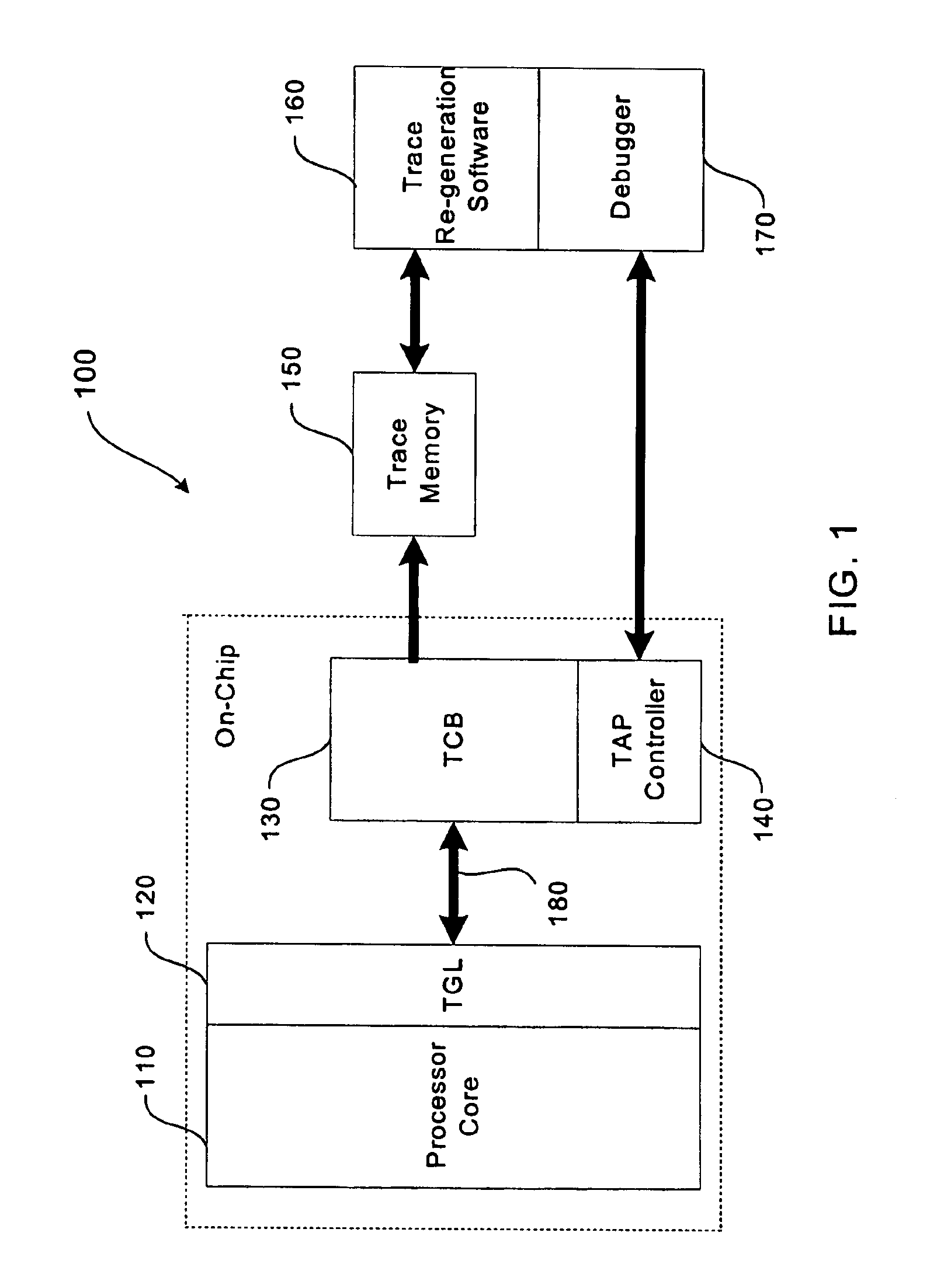
[0018]The provision of increased control and flexibility in the tracing process enables hardware, software, and computer engineers to effectively debug the operation of a computer system. These debugging efforts are enhanced when increased visibility is provided into the hardware and software state of the processor core. This is particularly true when dealing with embedded processors where specialized on-chip circuitry is often combined with the processor core. Support for these debug efforts is provided by an embodiment of a tracing system described below with reference to FIG. 1.
[0019]In the illustrated embodiment, tracing system 100 ...
PUM
 Abstract
Description
Claims
Application Information