
Floor saver toilet flange

a toilet flange and floor technology, applied in water closets, water installations, construction, etc., can solve the problems of rotted floor replacement, substantial damage, and leakage of toilet water, and achieve the effect of preventing water leakage from toilets

Active Publication Date: 2006-07-04
FLUSHING FLANGE
View PDF26 Cites 42 Cited by
  • Summary
  • Abstract
  • Description
  • Claims
  • Application Information

AI Technical Summary

Benefits of technology

"The present invention provides a toilet leak containment assembly for preventing water leaks from a toilet during flushing onto the support flooring into which the toilet is attached. The assembly includes a leak collector for collecting water leaks during flushing, an outlet pipe for channeling the leaks into the plumbing drain pipe, and a leak seal assembly for sealing between the toilet base and the leak collector, and between the flow channel and the interior toilet passage. The attachment flange attaches the leak collector to the support flooring, the collector pan allows the toilet to be mounted to the leak collector, and the flow channel directs water leaks into the plumbing drain pipe. The technical effect of this invention is to prevent water leaks from a toilet during flushing and to provide a convenient and effective solution for containing the leaks."

Problems solved by technology

One of the most common and more frustrating home repairs that needs to be made is the replacing of a rotted floor underneath a toilet caused by leakage over time.
With the existing toilets and pipes, it is a foregone conclusion that, over time, some leakage will occur when a toilet flushes.
The amount of water that does not go directly into the pipe should be forced down into the pipe over time and not be allowed to make contact with the floor or sub-floor where it can rot the floor and cause substantial damage.
While this system works initially, over time it begins to fail and allows water to reach the sub-floor.
As the years and seasons progress, the alternating hot and cold weather expands and contracts the wax seal, thus leaving gaps in the holes the seal had once filled on the toilet flange.
By leaving these areas exposed, the water from any leakage may now seep into these holes and begin to damage the sub-floor.

Method used


Image

  • Floor saver toilet flange
  • Floor saver toilet flange
  • Floor saver toilet flange

Examples


Embodiment Construction

[0018]Referring now in more detail to the drawings, the invention will now be described in more detail.

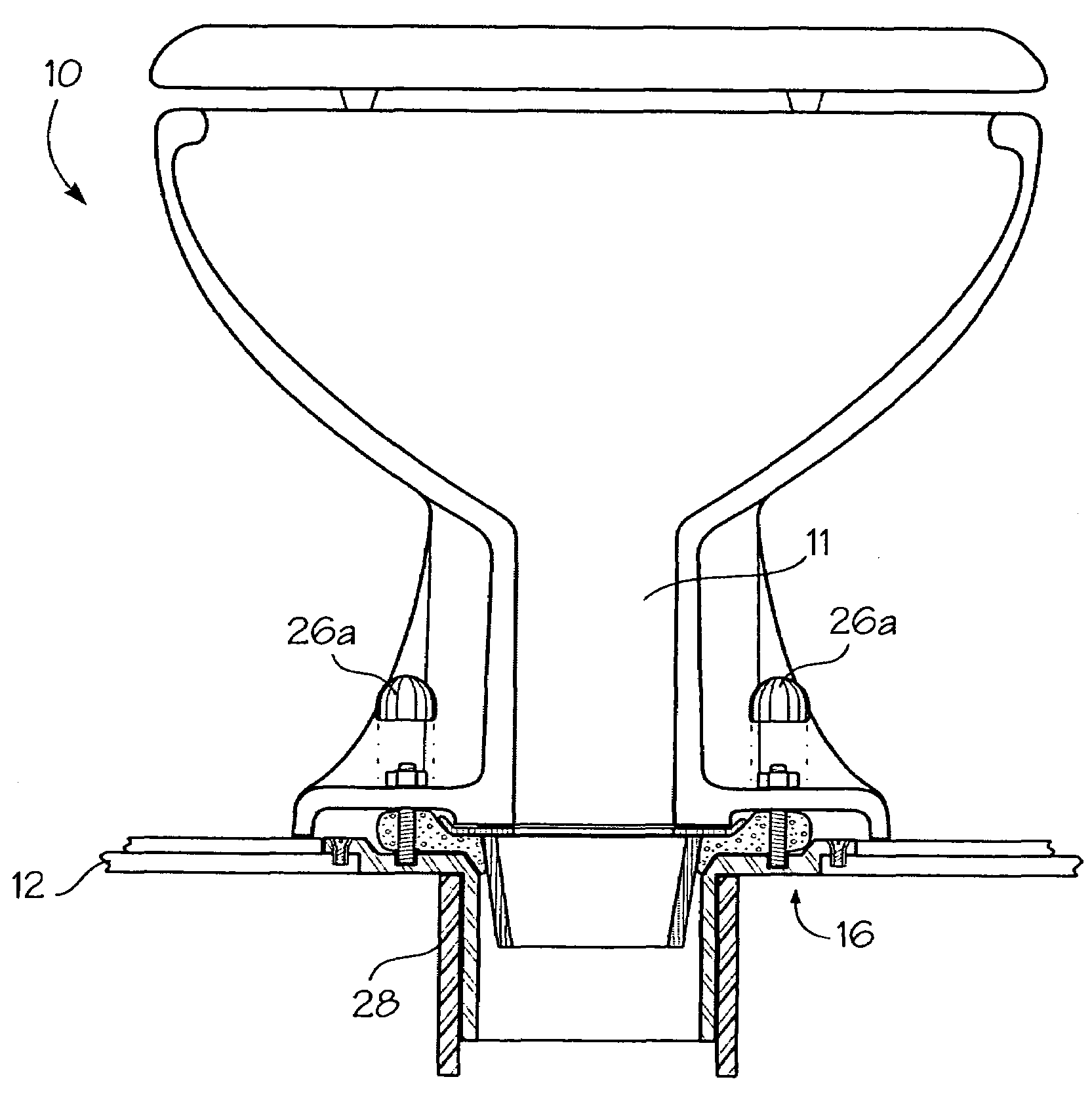
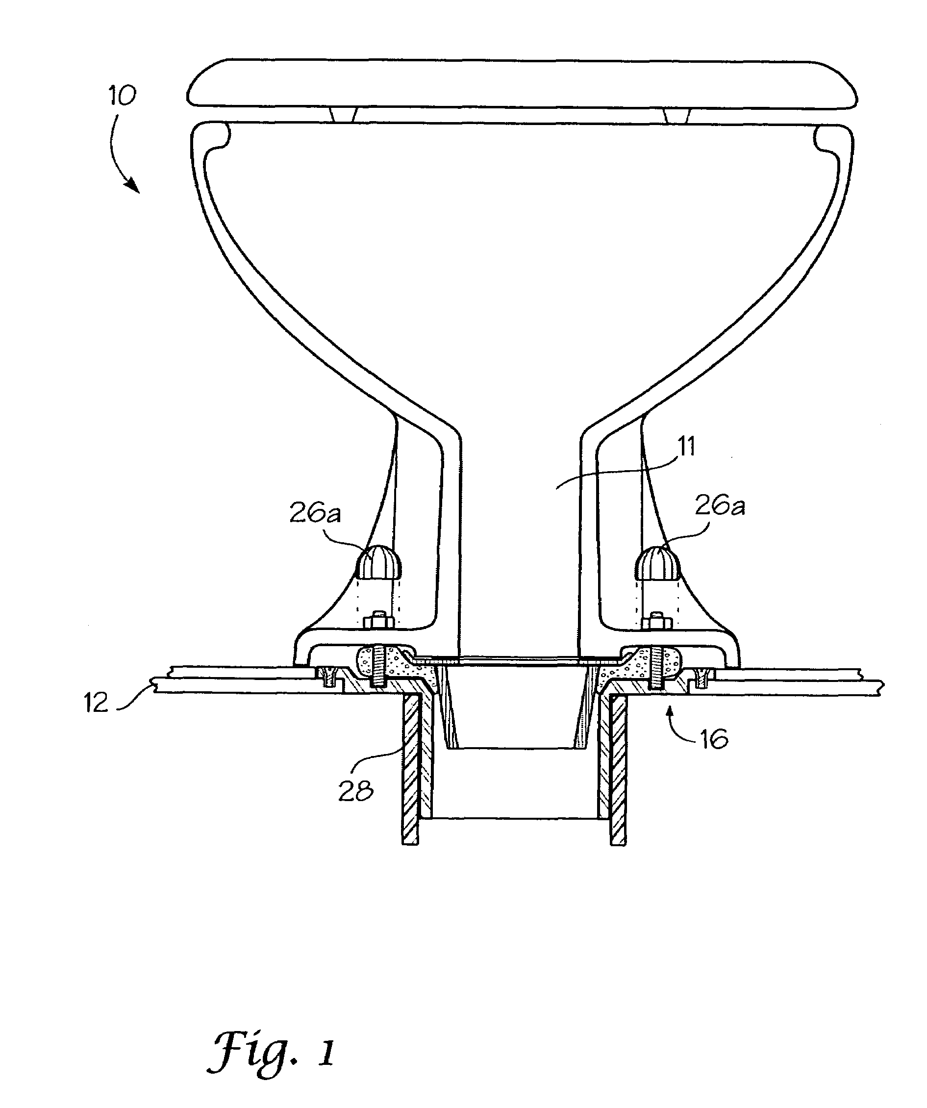
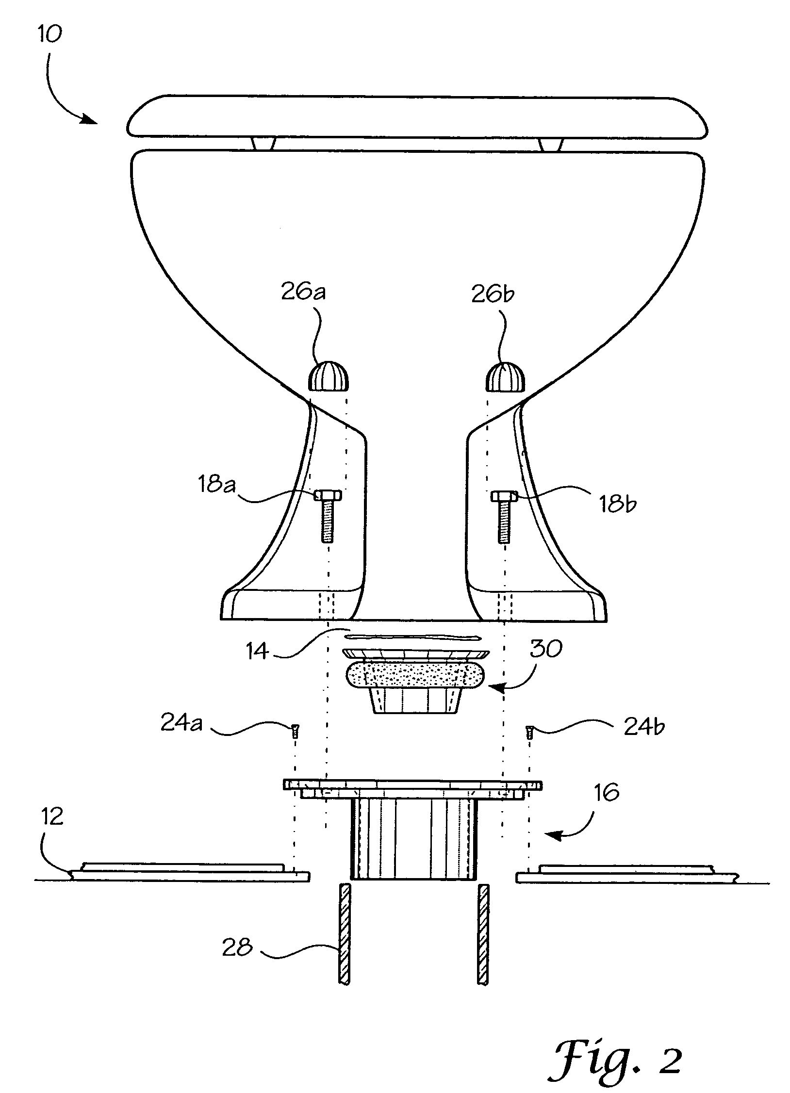
[0019]Referring now to FIG. 1, the invention is shown as having been installed into its environment. As can be seen, toilet 10 rests on sub-floor 12. Attached to sub-floor 12 is leak collector 16. Leak collector 16 is made up of an attachment flange 19, a collector pan 20 and an outlet pipe 22, as shown in FIGS. 5A and 5B.

[0020]Leak collector 16 is shown in more detail in FIGS. 5a and 5b. As can be seen, attachment flange 19 contains four attachment openings to allow attachment of the leak collector to the sub-floor. Collector pan 20 serves two purposes. First, it collects any water leaks and channels them to outlet pipe 22. Second, there are two mounting elements 20a and 20b provided in collector pan 20 for mounting a toilet to the collector pan. Note that in FIG. 5b, the mounting elements are mounting openings that do not extend into the support flooring of the house. Rather they...


PUM


Abstract

A toilet leak containment assembly for preventing water leaks from a toilet during flushing onto the support flooring into which the toilet is attached. The leak containment assembly contains a leak collector for installation between the toilet base and the support flooring for preventing the water leaks onto the support flooring during flushing. The leak collector contains an attachment flange for attaching the leak collector to the support flooring, a collector pan for collecting water leaks during flushing, and an outlet pipe in fluid communication with the collector pan for channeling the leaks into the plumbing drain pipe. It also contains a leak seal assembly for installation and sealing between the toilet base and the leak collector. The leak seal assembly contains a flow channel for channeling water flow into the outlet pipe of the leak collector, and a seal for sealing between the toilet base and the leak collector.

Description

BACKGROUND OF THE INVENTION[0001]One of the most common and more frustrating home repairs that needs to be made is the replacing of a rotted floor underneath a toilet caused by leakage over time. With the existing toilets and pipes, it is a foregone conclusion that, over time, some leakage will occur when a toilet flushes. The amount of water that does not go directly into the pipe should be forced down into the pipe over time and not be allowed to make contact with the floor or sub-floor where it can rot the floor and cause substantial damage.[0002]Traditionally, a toilet flange is placed in the sub-floor that receives the toilet bowl itself and the plumbing pipe and connects the two. These traditional flanges have four large areas for the placement of screws connecting the toilet to the toilet flange and four additional screws for mounting the flange to the sub-floor. The holes that are used for the screws that connect the toilet to the flange allow for much exposed sub-floor upon...

Claims


Application Information

Patent Timeline
Patent Type & Authority Patents(United States)
IPC IPC(8): E03D11/14E03D11/00E03D11/16
CPCE03D11/16
Inventor FLUSHING, JAY DAVID
Owner FLUSHING FLANGE
Learn More