
Vertical tubular bagging machine

a vertical tubular and bagging machine technology, applied in the direction of wrapping/bundling articles, paper/cardboard containers, containers, etc., can solve the problems of less suited for continuous foil run and lateral removal of fill pipes

Active Publication Date: 2006-07-04
ROVEMA
View PDF13 Cites 12 Cited by
  • Summary
  • Abstract
  • Description
  • Claims
  • Application Information

AI Technical Summary

Benefits of technology

"The invention is a vertical tubular bagging machine that allows for easy removal of the lateral fill-tube and good support of the foil web. The machine has a shoulder sleeve formed of two separate parts that can be separated to remove the fill pipe. The machine also has a conveyor worm that can be easily removed, and a device for adjusting and locking the space between the two troughs in the fill pipe. The technical effects of the invention include improved bagging efficiency, simplified maintenance, and better service friendliness."

Problems solved by technology

The known design has the disadvantage that the fill pipe can be removed laterally only when the forming shoulder is first removed.
The known forming element has the disadvantage that it is less suited for a continuous foil run since the incoming foil web is hardly supported.

Method used


Image

  • Vertical tubular bagging machine
  • Vertical tubular bagging machine
  • Vertical tubular bagging machine

Examples


Embodiment Construction

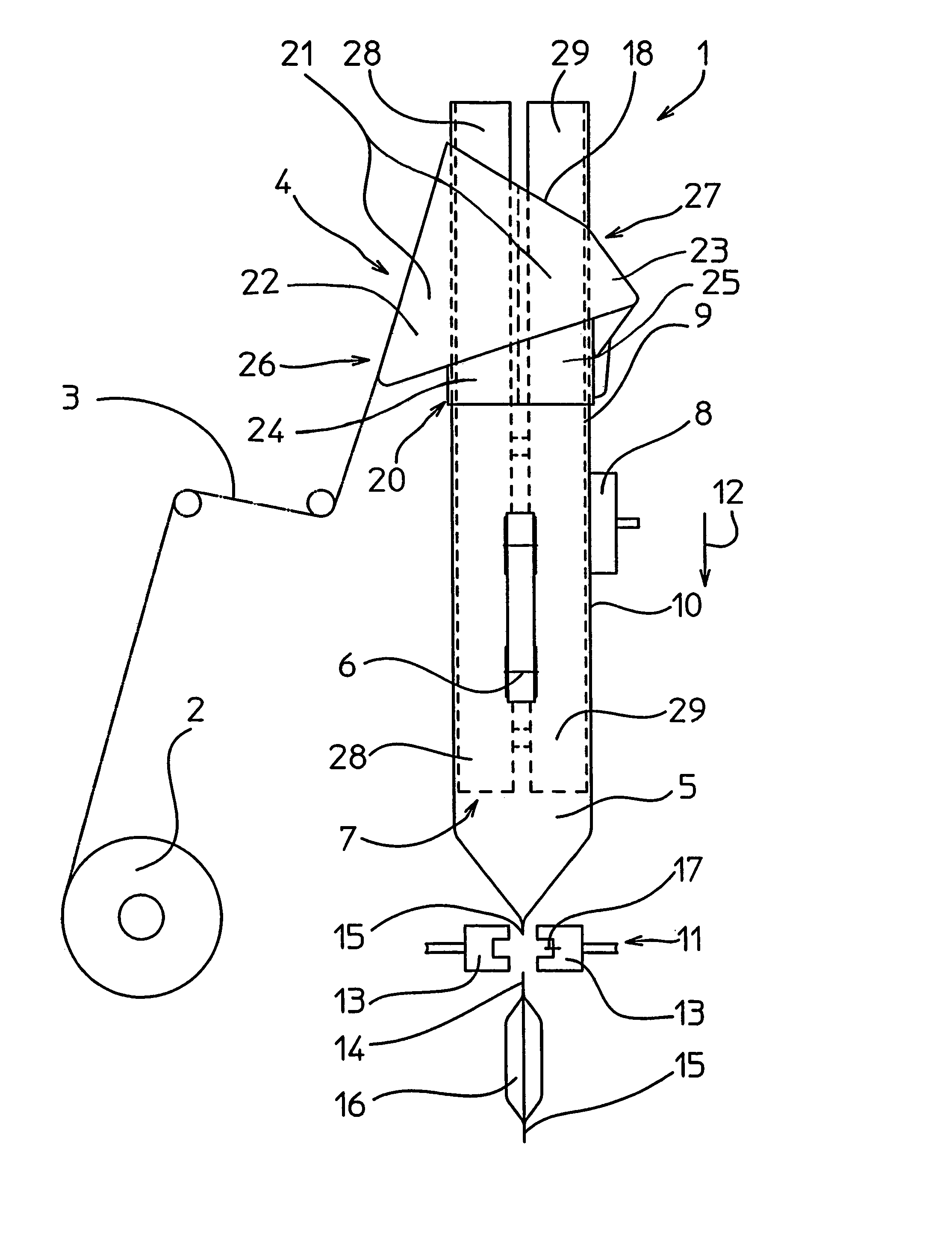
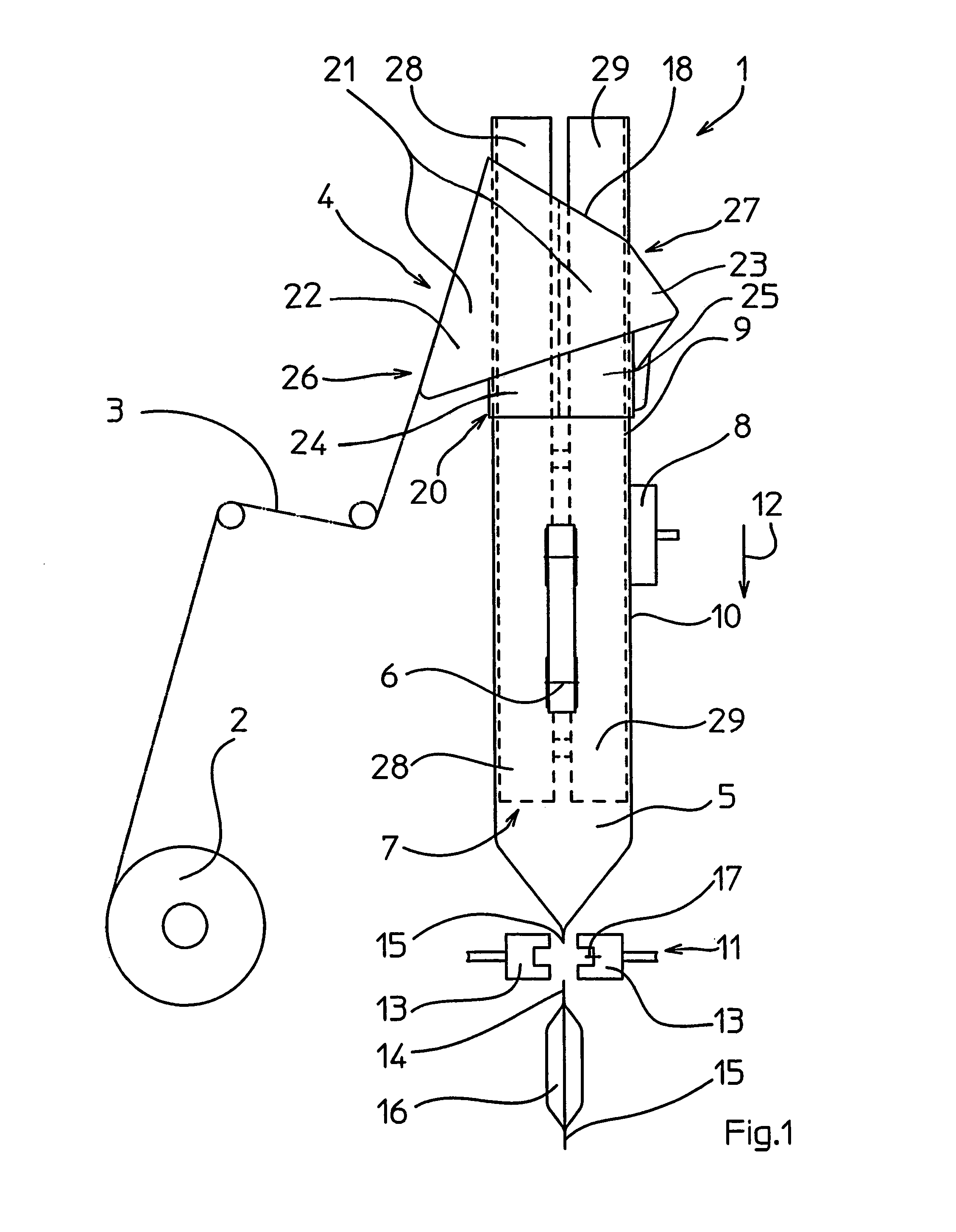
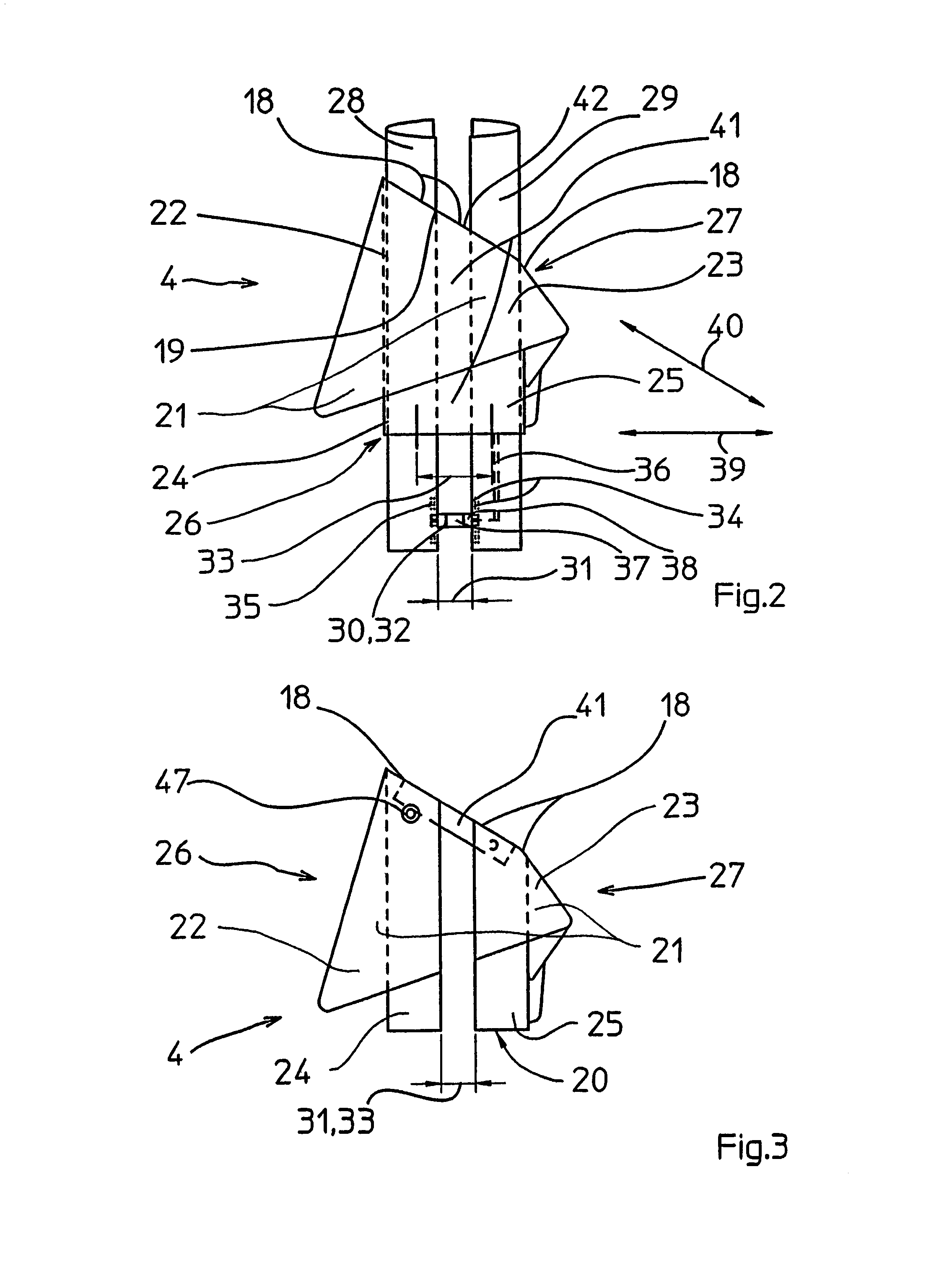
[0024]A foil web 3 is in a vertical tubular bagging machine 1 unwound from a storage roll 2 (FIG. 1). A forming shoulder 4 is used to reshape the foil web 3 into a foil tube 5. A foil-removing means 6 is utilized to further transport the foil web 3 and the foil tube 5. A vertically aligned fill pipe 7 is provided for receiving and filling of the foil tube 5. A longitudinal sealing device 8 is used to weld the edges 9 of the foil web 3 and thus to create a longitudinal sealing seam 10 of the foil tube 5. A cross-sealing device 11 with welding jaws 13, which can be moved against one another and which weld the foil tube 5 transversely with respect to its transport direction 12, is provided for creating of top seams 14 and bottom seams 15 on tubular bags 16.

[0025]A separating device 17 is utilized to separate the tubular bag 18 from the foil tube 5. The forming shoulder 4 has a guiding edge 18 on an upper edge 19 of shoulder connection 20 surrounding the fill pipe 7, and a shoulder slee...


PUM

PropertyMeasurementUnit
areaaaaaaaaaaa
relative heightaaaaaaaaaa
widthaaaaaaaaaa

Abstract

In order to be able to easily exchange the fill pipe in a vertical tubular bagging machine, where a flat foil web is reshaped on a forming shoulder into a foil tube running over a fill pipe, a forming shoulder is suggested which can be opened. A shoulder sleeve out of two separate sleeve parts is formed by this forming shoulder, a shoulder connection consists of two separate connection parts, each one sleeve part and adjoining connection part form one component, the two components describe the forming shoulder, and one component can be removed from the other component in order to be able to remove the fill pipe transversely with respect to the transport direction from the forming shoulder.

Description

FIELD OF THE INVENTION[0001]The invention relates to a vertical tubular bagging machine according to the generic terms of Claim 1.BACKGROUND OF THE INVENTION[0002]Vertical tubular bagging machines are used to create and fill tubular bags and are commonly known. A foil web unwound from a storage roller is reshaped on these machines into a vertically aligned foil tube by means of a forming shoulder. The lower tube end is filled, welded and separated from the remaining foil tube in order to create tubular bags filled in this manner.[0003]Depending on the type of bag to be created, varying forming shoulders are utilized. Generally a forming shoulder consists of a one-part shoulder sleeve, over which the flat foil web runs in order to reach a guiding edge. The foil web is then reshaped at the guiding edge in order to move on as a vertically aligned foil tube after passing the guiding edge. The foil tube runs thereby through an annular passage, which is defined on the outside by a shoulde...

Claims


Application Information

Patent Timeline
Patent Type & Authority Patents(United States)
IPC IPC(8): B65B11/00B29C65/18B29C65/74B65B9/20B65B9/22B65B59/00B65B59/04
CPCB65B59/04B65B9/20B65B9/22B65B59/00B29C65/18B29C65/745B29C66/1122B29C66/4312B29C66/8491B29C66/4322B65B59/003
Inventor BRAUN, HARALDBAUR, WALTER
Owner ROVEMA
Learn More