Collision energy-absorbing device

a technology of collision energy and energy-absorbing device, which is applied in the direction of shock absorbers, elastic dampers, instruments, etc., can solve the problems of deformation of the frame rails or otherwise damage the frame assembly, the cost of repairing damaged vehicle frame assemblies after a collision can be quite high, and the amount of collision energy is reduced to the remainder of the frame and the passenger compartmen

Inactive Publication Date: 2006-07-04
MAGNA INTERNATIONAL INC
View PDF34 Cites 38 Cited by
  • Summary
  • Abstract
  • Description
  • Claims
  • Application Information

AI Technical Summary

Problems solved by technology

In situations involving relatively high collision forces, transferring the collision energy directly to the vehicle frame assembly without some type of cushioning or dissipation can deform the frame rails or otherwise damage the frame assembly.
Repairing damaged vehicle frame assemblies after a collision can be quite expensive.
To solve this problem, it has been known to intentionally weaken end portions of the frame rails so that the weakened end portions collapse during collision and dissipate some or all of the collision energy, thereby reducing the amount of collision energy transmitted to the remainder of the frame and the passenger compartment.
These weakened end portions are referred to as “crush zones.” Providing these crush zones in the vehicle frame assembly adds significant complexity and increases the overall cost of manufacturing the vehicle frame assembly.
Another problem with these crush zones is that they often tend to buckle and fold outwardly rather than collapsing only in the direction of the impact force (i.e. the longitudinal direction of the vehicle).
The problem with this type of arrangement is that it is difficult to achieve satisfactory energy dissipation using only a pair of these accordion-type crush zones.
Specifically, the amount of deformation allowed in these accordion-type crush zones is limited by its width.
Further, in a frontal offset collision, impact occurs at one end of the bumper beam.

Method used


Image

  • Collision energy-absorbing device
  • Collision energy-absorbing device
  • Collision energy-absorbing device

Examples


Embodiment Construction

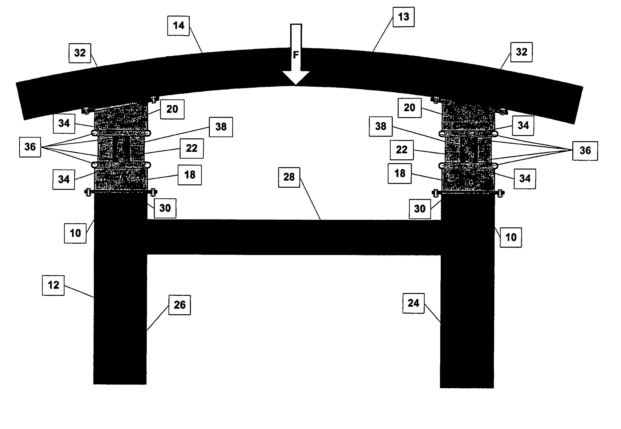
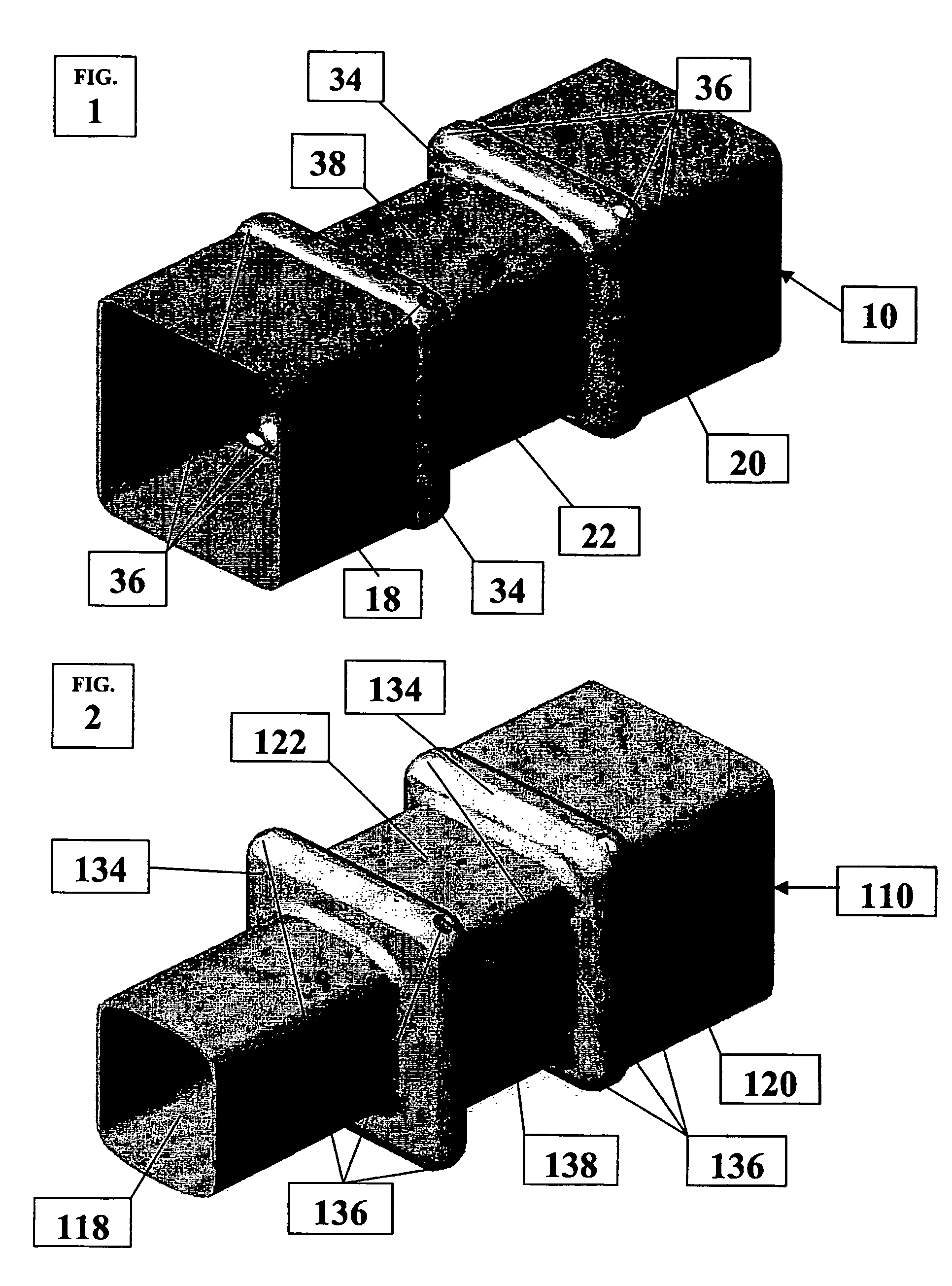
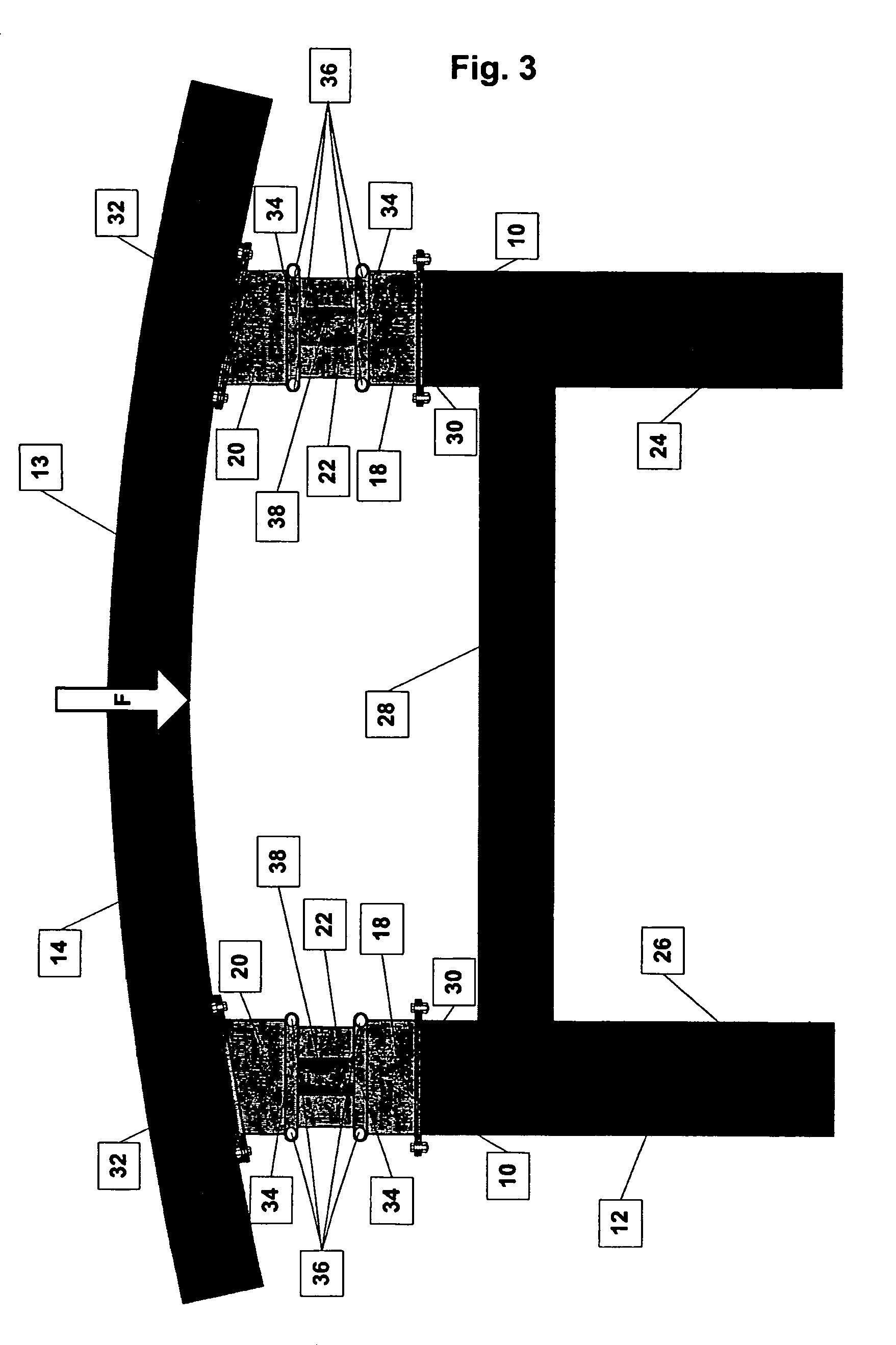
[0054]FIGS. 1, 3 and 4 illustrate one embodiment of a collision energy-absorbing device 10 constructed according to the principles of the present invention. As illustrated in FIG. 3, a pair of collision energy-absorbing devices 10 are mounted between a frame assembly 12 and a bumper beam 14 of a motor vehicle 13 at either the front or rear end of the motor vehicle 13. The bumper beam 14 is positioned to receive collision forces and transmit the collision forces to the pair of collision energy-absorbing devices 10 during impact conditions, such as a vehicle collision. The collision energy-absorbing devices 10, as will be further discussed, collapse during the impact conditions in order to dissipate energy and thus reduce the magnitude of collision forces being transmitted to the frame assembly 12 of the motor vehicle 13.

[0055]Referring to FIGS. 3 and 4, the vehicle frame assembly 12 includes right-hand and left-hand frame rails 24, 26 that extend in the fore and aft direction of the ...


PUM

PropertyMeasurementUnit
collision energy-aaaaaaaaaa
collision forcesaaaaaaaaaa
collision energyaaaaaaaaaa

Abstract

A collision energy-absorbing device includes a body member connected between the frame assembly of a motor vehicle and a bumper beam. The body member collapses as the bumper beam and the frame assembly are moved relatively toward one another during a vehicle collision. The body member has a first telescoping portion and a second telescoping portion that are connected by a connecting portion. The telescoping portions have different cross-sectional dimensions to enable the telescoping portions to move one within the other into collapsing telescoping relation as the body member collapses with the connecting portion being deformed and received between the telescoping portions. One or more protrusions extending from one of the telescoping portions interfere with relative movement of the other of the telescoping portions to retard movement of the telescoping portions into telescoping relation.

Description

CROSS REFERENCE TO RELATED APPLICATION[0001]This is the U.S. National Stage of PCT / US03 / 011908, filed Apr. 17, 2003, which in turn claims priority to U.S. Provisional Patent Application No. 60 / 373,607, filed Apr. 19, 2002, both of which are incorporated herein in their entirety by reference.FIELD OF THE INVENTION[0002]The present invention relates to a collision energy-absorbing device for mounting between a frame of a motor vehicle and a bumper beam at one end of the motor vehicle.BACKGROUND OF THE INVENTION[0003]In conventional vehicle frame assemblies, bumper beams are fixedly mounted to frame rails at the front and rear ends of the vehicle. During a front or rear end collision in the longitudinal direction of the vehicle, the collision forces are received by the bumper beam and transmitted to the frame assembly via the connection between the bumper beam and the frame rails. In situations involving relatively high collision forces, transferring the collision energy directly to th...

Claims


Application Information

Patent Timeline
Patent Type & Authority Patents(United States)
IPC IPC(8): B60R19/26B60R19/24B60R19/34C12Q1/68F16F1/00F16F3/02F16F6/00F16F7/12F16F9/46G05D19/02
CPCB60R19/34F16F1/00F16F6/00F16F7/125F16F3/02C12Q1/6886F16F2230/0052F16F2226/02
Inventor LONGO, THOMAS W.
Owner MAGNA INTERNATIONAL INC
Why Eureka
Try Eureka