Droplet ejecting head

a technology of droplets and ejectors, which is applied in the direction of measuring apparatus components, instruments, printing, etc., can solve the problems of inability to print high-quality images, inability to disclose the inkjet printer head, and suffer from cost, etc., to achieve no more complicated structure, less cost, and high viscosity

Inactive Publication Date: 2006-07-04
FUJIFILM HLDG CORP
View PDF6 Cites 41 Cited by
  • Summary
  • Abstract
  • Description
  • Claims
  • Application Information

AI Technical Summary

Benefits of technology

[0008]The present invention has been accomplished in order to solve the aforementioned problems of the prior art and has as an object providing a droplet ejecting head that is less costly, no more complicated in structure than the conventional inkjet printer head and which yet allows a fluid of high viscosity to be ejected in droplets with high efficiency.

Problems solved by technology

However, the recording paper for use in printing is mainly of dedicated type which is comparatively expensive and if plain paper having fairly high water absorbency is used, ink that has struck the surface of the paper will blot there, making it occasionally impossible to print high quality image.
However, the inkjet printer head disclosed in JP 11-10878 A suffers the problem of being costly since it has at least two heating elements.
What is more, the use of plural heating elements is susceptible to defects and the service life of the head is prone to be shortened.
This complicates the structure of the head, not only shortening its service life but also increasing the production cost.

Method used


Image

  • Droplet ejecting head
  • Droplet ejecting head
  • Droplet ejecting head

Examples


Embodiment Construction

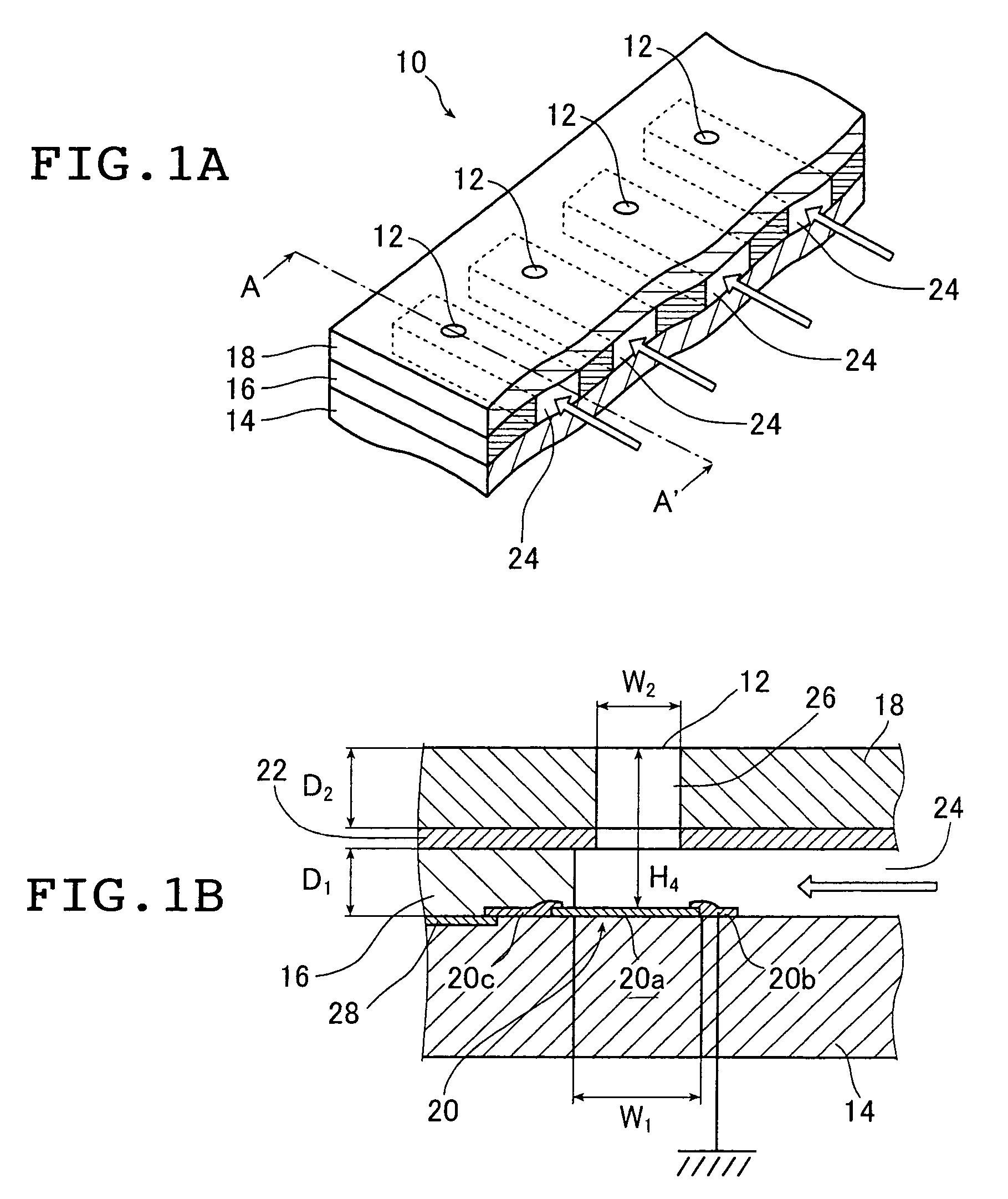
[0020]On the pages that follow, the droplet ejecting head of the invention is described in detail with reference to the preferred embodiments depicted in the accompanying drawings.

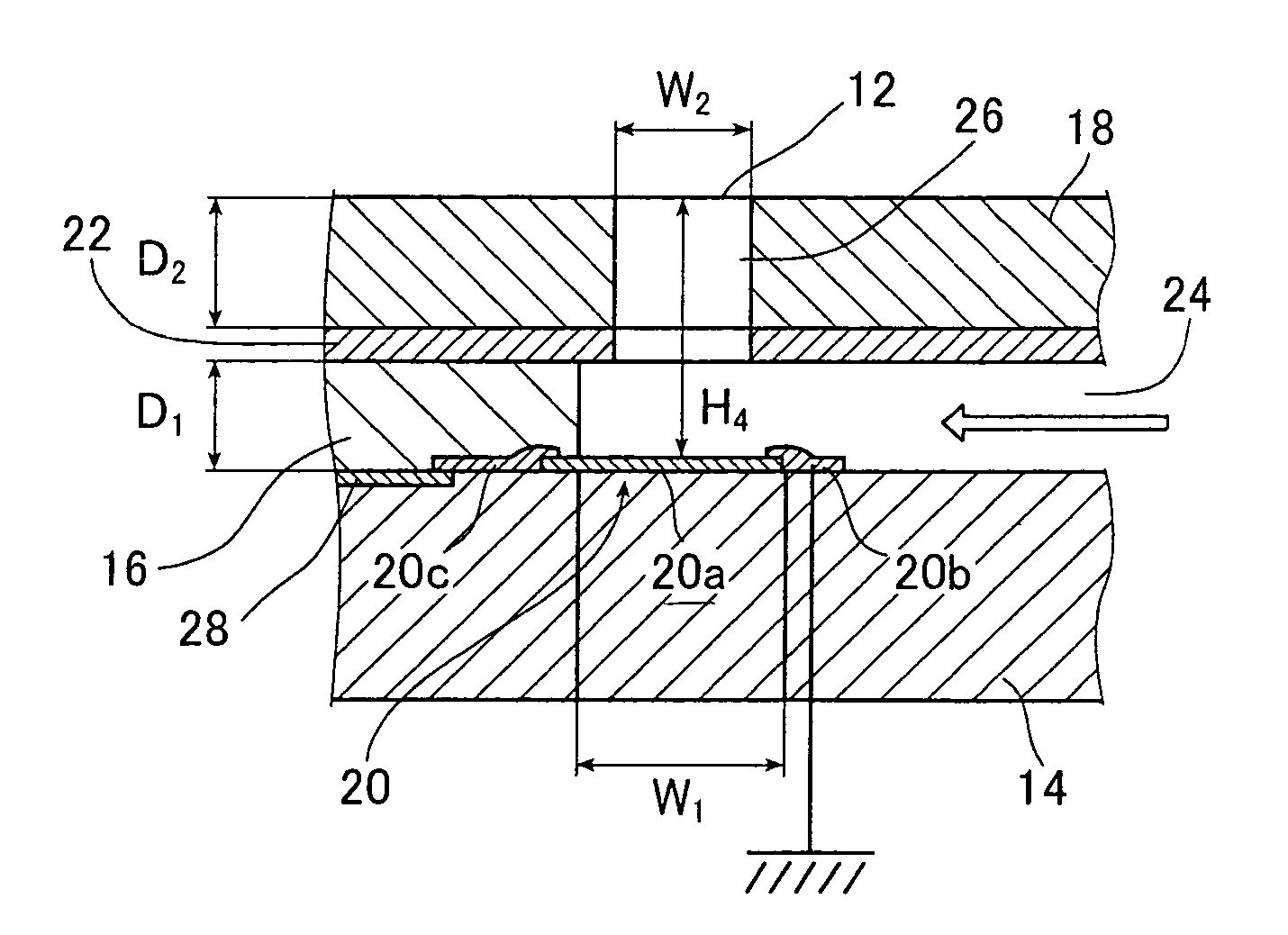
[0021]FIG. 1A is a perspective view showing diagrammatically an exemplary droplet ejecting head 10 according to the invention and FIG. 1B is section A–A′ of the droplet ejecting head 10 shown in FIG. 1A.

[0022]The droplet ejecting head 10 has a number of circular ejection ports 12 formed in one direction at specified intervals and through those ejection ports 12, droplets of a fluid more viscous than the ink commonly used on inkjet printer heads are ejected. Each ejection port 12 has an ejection unit that is so designed that droplets are ejected through the ejection port 12.

[0023]The droplet ejecting head 10 mainly comprises a Si substrate 14, a spacer layer 16 and a nozzle plate 18.

[0024]As shown in FIG. 1B, a heating element 20 (a first heating element) is formed on a surface of the Si substrate 14 and it...


PUM


Abstract

The droplet ejecting head includes heating elements each of which has a thermal energy applying surface which imparts energy to a viscous fluid with a viscosity of at least 20 mPa·sec so as to evolve a bubble, fluid supply channels each of which has the heating element on a wall and supplies the fluid toward the heating element and ejection nozzles through each of which the fluid is ejected as a droplet and each of which is in a position opposite the energy applying surface of the heating element across the supply channel. A distance between the energy applying surface and a foremost end of the ejection nozzle from which the droplet is ejected is in a range of from 2 μm to 8 μm or the distance is smaller than a growth height of the bubble that has evolved in the fluid by means of the heating element and which has been left to expand by itself until its internal pressure once exceeding one atmosphere decreases to a point below one atmosphere.

Description

BACKGROUND OF THE INVENTION[0001]This invention relates to a droplet ejecting head which heats a viscous fluid with heating elements to produce bubbles that cause the fluid to be ejected as droplets.[0002]One of the inkjet printers that have become popular today are of a type that uses a thermal inkjet printer head in which part of ink is abruptly heated to form a bubble in the ink and ink droplets are propelled and ejected by the expansion force of the bubbles formed in the ink. With this type of ink jet printers, high quality image can be easily printed on recording paper. However, the recording paper for use in printing is mainly of dedicated type which is comparatively expensive and if plain paper having fairly high water absorbency is used, ink that has struck the surface of the paper will blot there, making it occasionally impossible to print high quality image.[0003]In order to solve this problem, one may think of employing ink of comparatively high viscosity so that it will ...

Claims


Application Information

Patent Timeline
Patent Type & Authority Patents(United States)
IPC IPC(8): B41J2/05B41J2/135B41J2/14
CPCB41J2/1404B41J2/1412B41J2/14137B41J2/14129B41J2002/14387
Inventor YAMAMOTO, RYOICHIKODAMA, KENICHISANADA, KAZUO
Owner FUJIFILM HLDG CORP
Why Eureka
Try Eureka