Thermal fuse containing bimetallic sensing element

Inactive Publication Date: 2006-07-04
HONEYWELL INT INC
View PDF15 Cites 17 Cited by
  • Summary
  • Abstract
  • Description
  • Claims
  • Application Information

AI Technical Summary

Benefits of technology

[0006]In a second aspect of the invention, the non-resetable component is a high-temperature non-conductive material that interrupts an el

Problems solved by technology

Some commercially available thermal fuses have limited temperature capability.
However, there is potential for the solder bridge to migrate back into place under vibration or changes in unit orientation, causing a re-closure of the switch

Method used


Image

  • Thermal fuse containing bimetallic sensing element
  • Thermal fuse containing bimetallic sensing element
  • Thermal fuse containing bimetallic sensing element

Examples


Embodiment Construction

[0010]The present invention is a nonresetable, bimetallic thermal switch. The trip temperature for a bimetallic thermal switch is based on the characteristics of a bimetallic disk that is included within the thermal switch. Bimetallic disks can be manufactured to trip at a temperature over a range of temperatures greater than solder-type thermal switches.

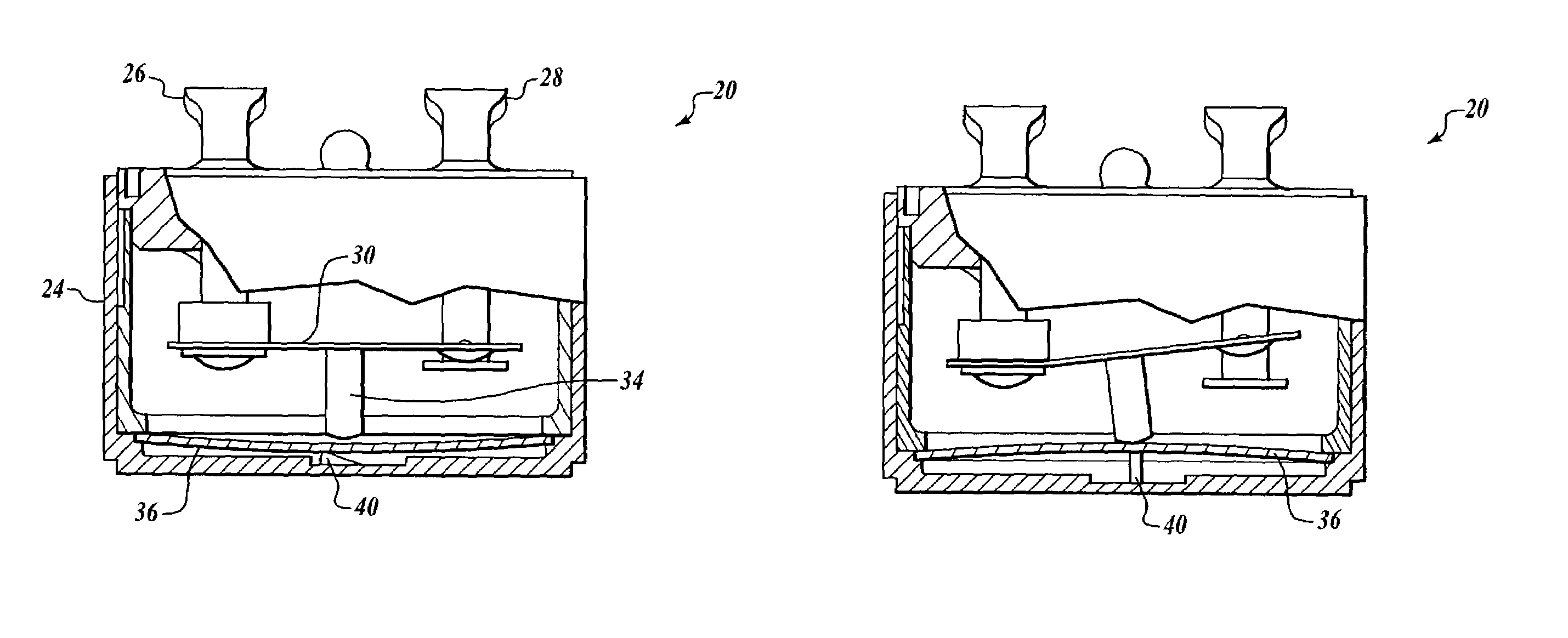
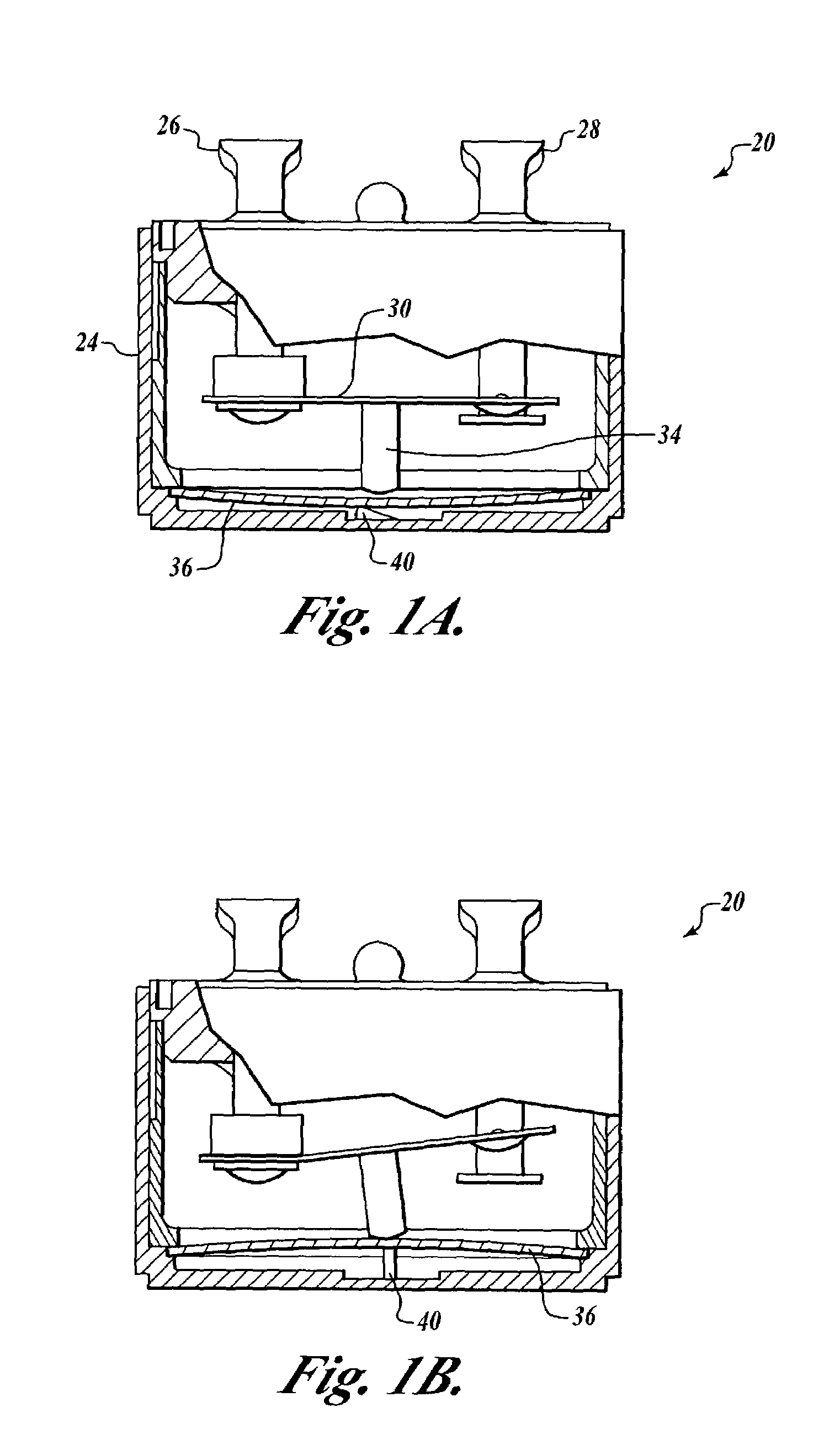
[0011]FIGS. 1A and B illustrate an embodiment of a non-resetable, bimetallic thermal switch 20 formed in accordance with the present invention. The non-resetable, bimetallic thermal switch 20 includes a hermetically sealed housing 24 that includes electrical terminals 26 and 28 that extend from outside the housing 24 to inside the housing 24. A flexible conducting beam 30 physically and electrically attaches to the first terminal 26 within the housing 24. A non-conducting plunger 34 is attached to the conducting beam 30 at some predefined distance from the first terminal 26. A bimetallic disk 36 is located at a base of the interior ...


PUM


Abstract

A non-resetable, bimetallic thermal switch. The bimetallic thermal switch includes a bimetallic element, first and second electrical contacts, and a component for electrically connecting and disconnecting the first and second electrical contacts based on movement of the bimetallic element. The switch also includes a non-resetable component configured to disallow electrical reconnection of the first and second electrical contacts after an electrical disconnection has occurred between the first and second electrical contacts.

Description

BACKGROUND OF THE INVENTION[0001]Some commercially available thermal fuses have limited temperature capability. These thermal fuses use a solder that is alloyed to melt at a desired trip temperature. The solder is suspended between two points in a circuit (bridge). The solder “bridge” melts and falls away at the trip temperature, thereby opening the circuit (fuse). Other thermal fuses use the same solder, but contain a spring and contact bar. When the solder reaches its melting temperature, the spring pushes the bar away from the contacts thereby opening the circuit. Thus, solder fuses are not resetable, which is important for many applications. However, there is potential for the solder bridge to migrate back into place under vibration or changes in unit orientation, causing a re-closure of the switch to occur. Also, solder-type thermal fuses have a limited temperature range due to the melting point of the alloyed solder.[0002]Bimetallic thermal switches can be designed to trip ove...

Claims


Application Information

Patent Timeline
IPC IPC(8): H01H37/54
CPCH01H37/5409H01H2037/705H01H2037/526
Inventor DAVIS, GEORGE D.SCOTT, BYRON G.
Owner HONEYWELL INT INC
Why Eureka
Try Eureka