Fuel tank system
a fuel tank and system technology, applied in the direction of liquid fuel feeders, machines/engines, electric control, etc., can solve the problem of not being able to detect abnormalities in fuel supply switches, and achieve the effect of preventing abnormal determination of fuel supply switches and reducing power consumption
- Summary
- Abstract
- Description
- Claims
- Application Information
AI Technical Summary
Benefits of technology
Problems solved by technology
Method used
Image
Examples
first embodiment
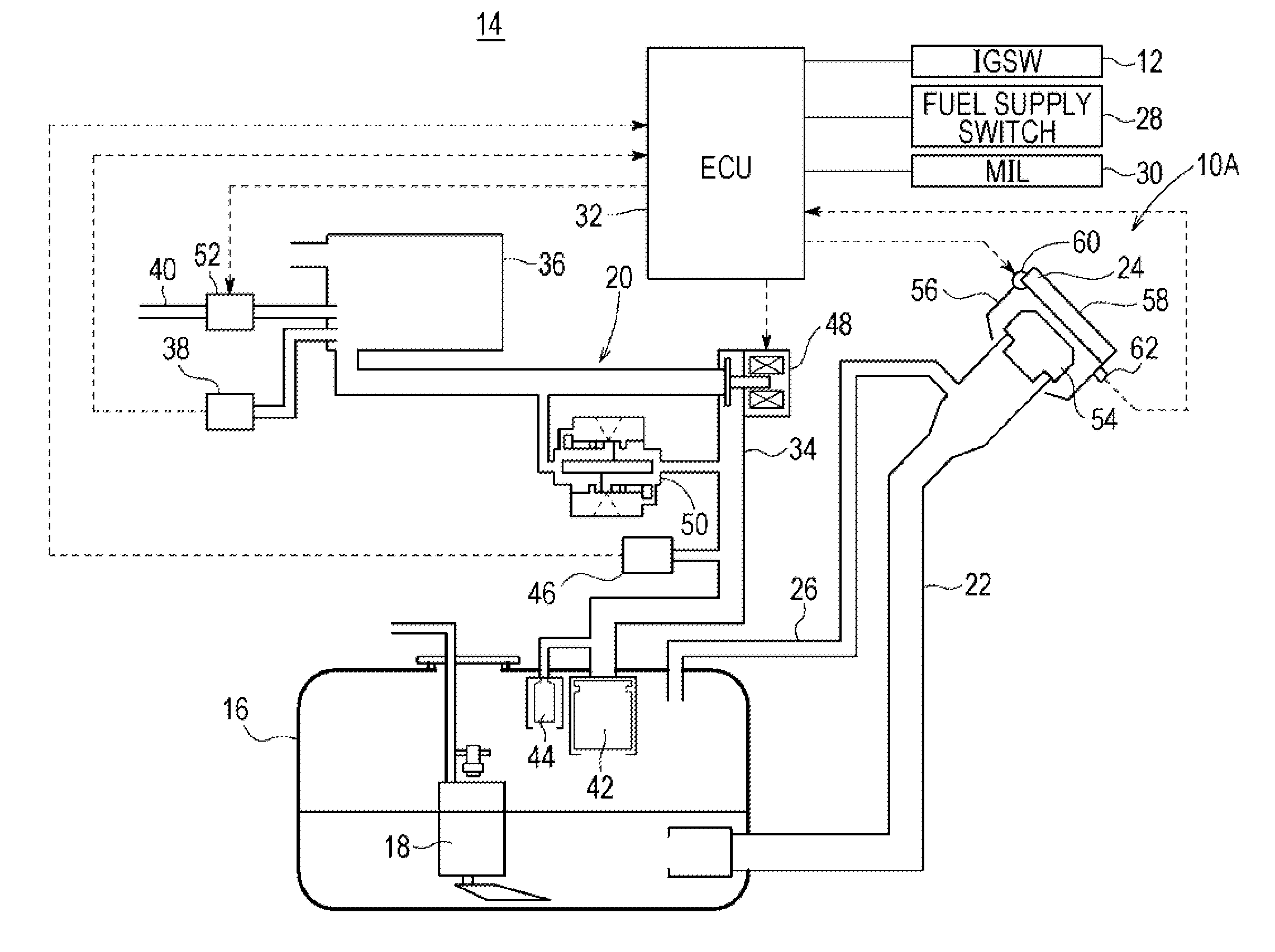
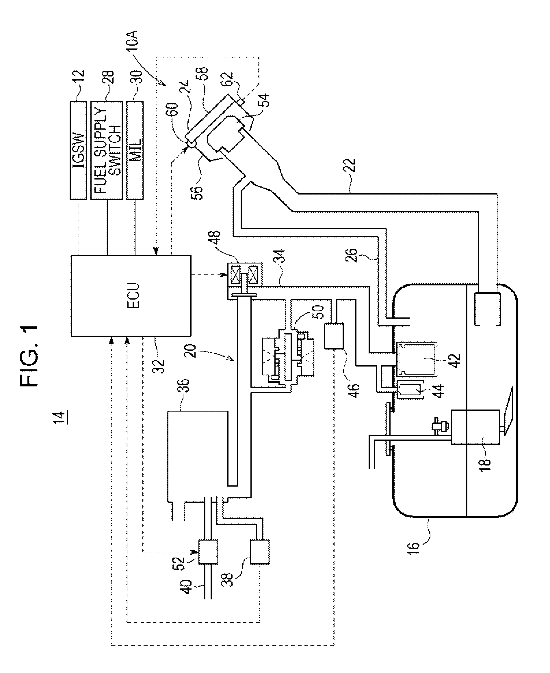
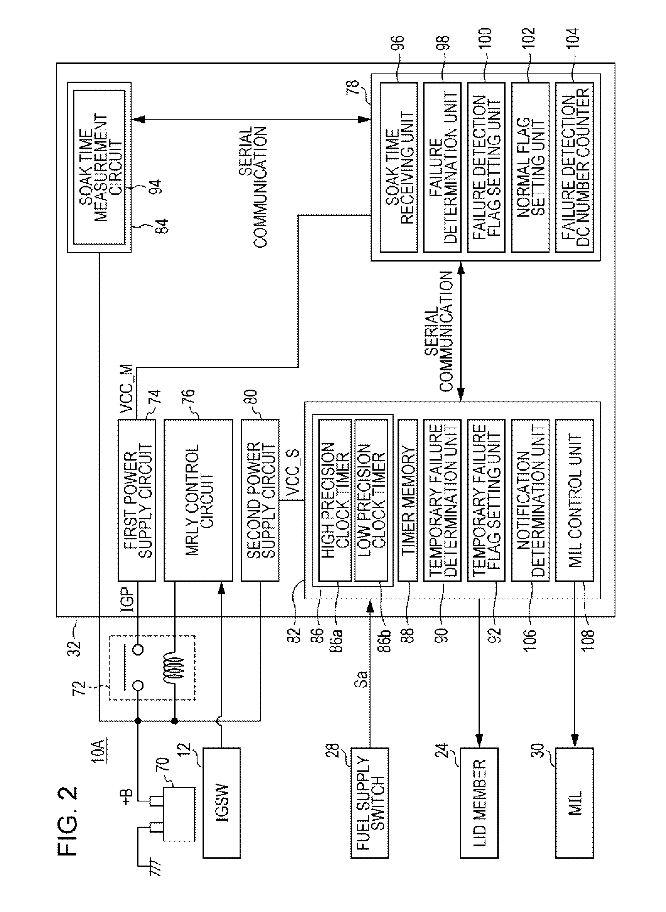
[0038]As illustrated in FIG. 1, a fuel tank system 10A according to a first embodiment of the present disclosure is applied to a vehicle 14 which has an ignition switch 12 for starting or stopping a power unit (an internal-combustion engine or an electric machine such as a motor) which is not illustrated. The fuel supply switch 28 is provided for opening a lid member 24 which closes a fuel supply port of a fuel tank 16. The fuel tank system 10A is for detecting a failure (abnormality) of a fuel supply switch 28 while the ignition switch 12 is off.
[0039]The fuel tank system 10A includes a fuel tank 16 in which liquid fuel (hereinafter simply referred to as fuel) is stored, a fuel pump 18 for guiding fuel to an internal-combustion engine which is not illustrated, an evaporated fuel treatment unit 20 for treating evaporated fuel of the fuel tank 16, a filler pipe 22 for supplying fuel into the fuel tank 16, a lid member 24 which is provided in the filler pipe 22 to close a fuel supply ...
second embodiment
[0084]Next, a fuel tank system 10B according to a second embodiment of the present disclosure will be described with reference to FIGS. 9 to 13. In the present embodiment, the elements having the same or similar functions and effects as or to those of the above-described first embodiment are labeled with the same reference symbols, and detailed description is omitted. In a similar manner, detailed description will be omitted in the third embodiment described below.
[0085]As illustrated in FIG. 9, an ECU 120 included in the fuel tank system 10B according to the present embodiment includes a main control unit 122 and a sub control unit 124. The main control unit 122 has the SOAK time receiving unit 96, the failure detection flag setting unit 100, the normal flag setting unit 102, the failure detection DC number counter 104, a first input time receiving unit 126, a failure determination unit (abnormality determination unit) 128, an insufficient time calculation unit 130, and an IGP setu...
third embodiment
[0115]Hereinafter, a fuel tank system 10C according to a third embodiment of the present disclosure will be described with reference to FIGS. 15 to 17.
[0116]As illustrated in FIG. 15, the ECU 150 in the fuel tank system 10C according to the present embodiment includes a main control unit 152 and a sub control unit 154. The main control unit 152 has the SOAK time receiving unit 96, a failure determination unit 156, and a failure detection flag setting unit 158.
[0117]The failure determination unit 156 determines whether or not a total time (total measured times) T0 of the first input time T1 and SOAK time T2 exceeds a predetermined failure determination time (third determination time) Tf, the first input time T1 being transmitted from the timer memory 88 to the main control unit 152, the SOAK time T2 being received by the SOAK time receiving unit 96. The failure detection flag setting unit 158 sets the failure detection flag based on a result determined by the failure determination un...
PUM
 Abstract
Description
Claims
Application Information
 - R&D
- Intellectual Property
- Life Sciences
- Materials
- Tech Scout
- Unparalleled Data Quality
- Higher Quality Content
- 60% Fewer Hallucinations
Browse by: Latest US Patents, China's latest patents, Technical Efficacy Thesaurus, Application Domain, Technology Topic, Popular Technical Reports.
© 2025 PatSnap. All rights reserved.Legal|Privacy policy|Modern Slavery Act Transparency Statement|Sitemap|About US| Contact US: help@patsnap.com


