Electric charging system and electric charger

a charging system and electric charger technology, applied in the direction of electric devices, batteries/cells, instruments, etc., can solve the problems of inability to accurately confirm the state of charge the difficulty of high-quality charging of the electric storage device, and the drop of voltage in the charging cable during charging. accurate determination, accurate calculation, accurate calculation

Active Publication Date: 2013-05-23
SUBARU CORP
View PDF0 Cites 40 Cited by
  • Summary
  • Abstract
  • Description
  • Claims
  • Application Information

AI Technical Summary

Benefits of technology

[0016]According to the present invention, a determination voltage that is compared with the supplied voltage at the electric charger side when the state of charge of the electric storage device is determined is updated on the basis of the voltage drop amount in the charging cable. Therefore, the state of charge of the electric storage device can be accurately determined on the basis of the supplied voltage from the electric charger, without being affected by the charging cable.
[0017]Further, since a reference point is set for the supplied voltage data on t

Problems solved by technology

However, since the charging cable has an electric resistance and an impedance, a voltage drop occurs in the charging cable during charging.
Thus, since a difference occurs between a supplied voltage the electric charger side and a received voltage at the electric vehicle, charging of the electric storage device is

Method used


Image

  • Electric charging system and electric charger
  • Electric charging system and electric charger
  • Electric charging system and electric charger

Examples


Embodiment Construction

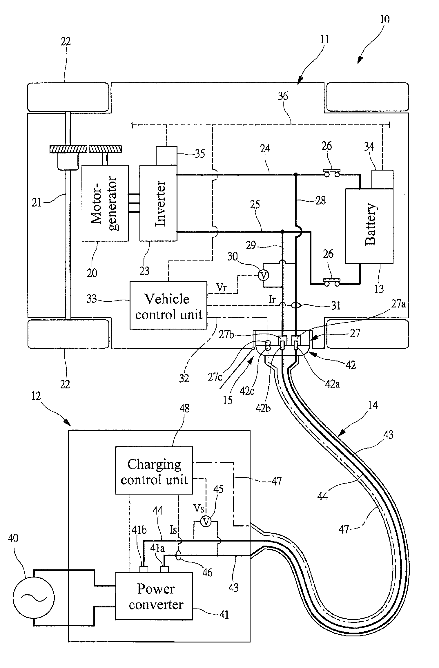
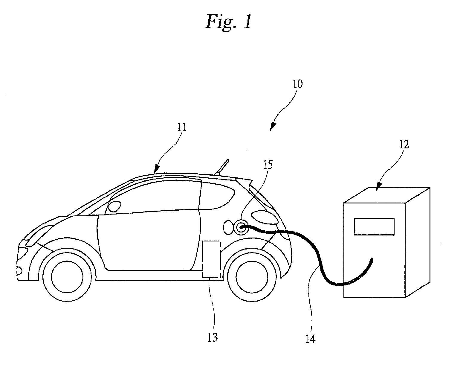
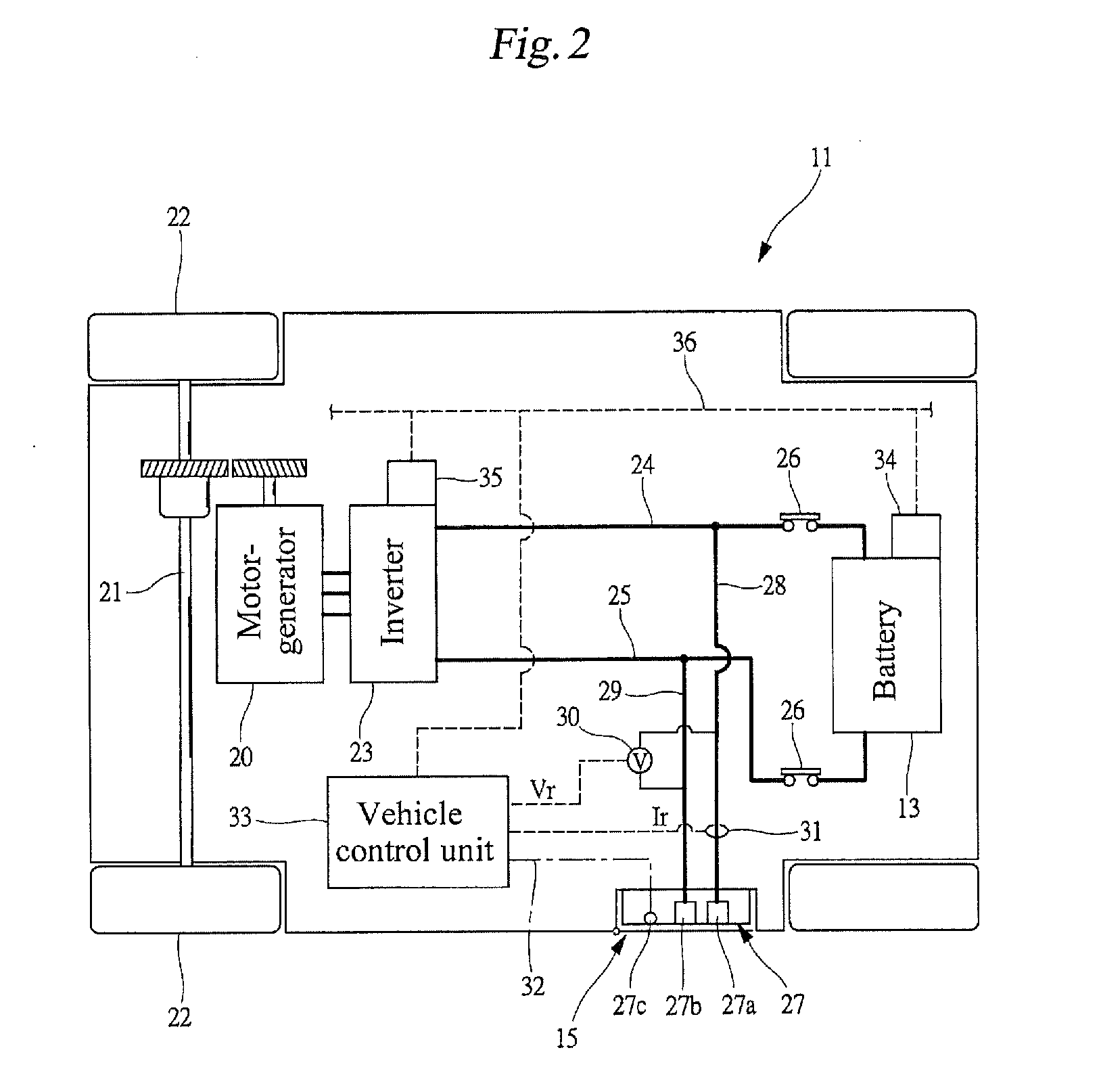
[0028]An embodiment of the present invention will hereunder be described with reference to the drawings. FIG. 1 is schematic diagram illustrating charging performed with an electric charging system 10 according to an embodiment of the present invention. FIG. 2 is a schematic diagram showing the internal structure of an electric vehicle 11 constituting the electric charging system 10. FIG. 3 is a schematic diagram showing the internal structure of an electric charger 12 constituting the electric charging system 10. As shown in FIG. 1, the electric vehicle 11 is equipped with a battery 13 as an electric storage device. When the battery 13 is charged, a charging cable 14 of the electric charger 12 is connected to a charging port 15 of the electric vehicle 11. The electric charger 12 charges the battery 13 to a predetermined voltage, while controlling the charging current or charging voltage supplied to the electric vehicle 11. The electric charger 12 can use a constant-current charging...


PUM


Abstract

There is provided an electric charging system in which an electric charger and an electric vehicle are connected by a charging cable. The electric charger calculates a voltage drop amount in the charging cable on the basis of a supplied current at the electric charger side and an electric resistance of the charging cable. The electric charger also compares a determination voltage with a supplied voltage at the electric charger side and determines that a battery has been charged to a fully charged state when the supplied voltage reaches the determination voltage. The determination voltage used for such full charge determination is updated by adding the voltage drop amount to a basic determination voltage that is set in advance.

Description

CROSS REFERENCES TO RELATED APPLICATIONS[0001]The present application claims priority from Japanese Patent Application No. 2011-252775 filed on Nov. 18, 2011, the entire contents of which are hereby incorporated by reference.BACKGROUND OF THE INVENTION[0002]1. Field of the Invention[0003]The present invention relates to an electric charging system and an electric charger, and, in particular, to a technology for preventing the erroneous determination of the state of charge of an electric storage device charged with an electric charger.[0004]2. Description of the Related Art[0005]In recent years, electric vehicles that are equipped with an electric motor for propulsion have been under development. When an electric storage device such as a battery that is installed at the electric vehicle is charged, a charging cable extending from an electric charger is connected to a charging port of the electric vehicle (see, for example, Japanese Unexamined Patent Application Publication No. 2009-8...

Claims


Application Information

Patent Timeline
IPC IPC(8): H02J7/00
CPCB60L3/003Y02T10/7055B60L7/14B60L11/1803B60L11/1816B60L11/1825B60L11/185B60L11/1877B60L2210/14B60L2230/12B60L2230/16G01R19/16542Y02T10/7005Y02T10/7088Y02T10/705Y02T10/7225Y02T90/163Y02T90/121Y02T90/14Y02T90/128Y02T90/127H02J7/0027H02J7/008H02J7/0086B60L3/04B60L53/14B60L50/51B60L53/31B60L53/11B60L50/66B60L53/18B60L53/305H02J2310/48Y02T10/70Y02T10/72Y02T10/7072Y02T90/12Y02T90/16H02J3/322H02J7/007182Y04S30/12Y02T90/167
Inventor OHTOMO, YOSUKE
Owner SUBARU CORP
Why Eureka
Try Eureka