End cap for a tubular light source

a tubular light source and end cap technology, applied in the direction of lighting and heating apparatus, lighting support devices, coupling device connections, etc., can solve the problems of exposing the installer to potential hazards, touching the exposed end cap and receiving an electrical shock, etc., to reduce the risk for the installer.

Inactive Publication Date: 2018-03-20
SIGNIFY HLDG BV
View PDF26 Cites 5 Cited by
  • Summary
  • Abstract
  • Description
  • Claims
  • Application Information

AI Technical Summary

Benefits of technology

[0007]The present invention is based on the idea of providing an end cap for a tubular light source having double safety mechanisms, i.e. using a pair of spring loaded switching elements, which both must be individually actuated before electricity can be provided from the socket into the light source. According to the present invention, to prevent this problem, both safety mechanisms must be actuated in the unconnected end before the connector pins will carry a live voltage. An advantage of the present invention is that double safety mechanisms may reduce the risk of accidently form such an electrical connection and thus also reduce the risk of exposing the installer to the potential hazard of receiving an electrical shock through an unconnected end cap. A further advantage of the end cap according to the present invention is that spring loaded switching elements may increase safety during installation and un-installation in comparison to prior art solutions, since the springs may more or less automatically return the switching elements to their non-actuated states during un-installation. The spring loaded switching elements determine whether an electronic connection is made between the pins on one side of the tubular light source and the pins on the other side of the tubular light source. The protruding first spring loaded switching element is, in an exemplary embodiment, designed and configured to be depressed when mounted in the intended fixture. The function of a mechanical solution, such as is provided by means of the pair of spring loaded switching elements, is not dependent of a ballast type, in comparison to employing a circuitry based approach of a safety arrangement, and may comply with the different sockets that are used in current fixtures. As such, the shape of the mechanical solution should comply with all mechanical constraints provided by the lamp holders and the standard outline of the lamp. Moreover, since the switching elements are spring loaded, a certain pressure is required to actuate the switching elements. This may also reduce the risk of accidently actuating the switching elements.
[0008]According to another embodiment of the present invention, the first and second spring loaded switching elements are arranged in their actuated states by applying a translational force onto a front portion of the first and the second spring loaded switching element, respectively.
[0009]By the term “front portion” should, in the context of the present specification, be understood to relate to a portion of the switching element accessible for an installer of the tubular light source. The front portion may for example be a portion of the switching element protruding through the housing portion of the end cap or it may be a portion of the switching element accessible through a hole in the housing portion.
[0010]By the term “translational force” should, in the context of present specification, be understood to relate to a force that produces movement of the switching element in a non-rotational direction.
[0011]A further advantage is that a simple way of actuating a switching element is provided, which may not require any particular skill or knowledge when installing the tubular light source. A still further advantage is that the first switching element may be automatically actuated when installing the end cap in the socket since the socket will apply the needed force on the protruding part, i.e. front portion, of the first switching element when inserted therein. By having a switch which only closes an electrical circuit when the connector pins are out of reach for the installer significantly reduces the risk for the installer of receiving an electrical shock when installing the tubular light source.
[0012]Further, the first switching element may be configured to return to its non-actuated state when no translational force is applied onto its front portion. This may be advantageous when un-installing the tubular light source. In this case, the electrical connection between the connector pins at a side which is still connected to a socket and the connector pins at the unconnected end cap is interrupted as soon as the translational force of the first spring loaded switching element is removed, e.g. as soon as the end cap is removed from the socket.

Problems solved by technology

As a result, installation of retrofitted LED tubular light sources may be a safety hazard as it is possible to first install one end cap in the mains connected fixture while having the other end cap still exposed and carrying a live potential on the connection pins of the exposed cap.
Thus, there is a risk that the installer touches the exposed end cap and receives an electrical shock.
However, a safety switch according to US2010 / 018178 may in some cases be unintentionally engaged when the installer is inserting the first end of the tubular light source while having already inserted the second end into the fixture, thereby still exposing the installer to potential hazard as the unconnected end cap may then have a live potential.

Method used


Image

  • End cap for a tubular light source
  • End cap for a tubular light source
  • End cap for a tubular light source

Examples


Embodiment Construction

[0038]The present invention will now be described more fully hereinafter with reference to the accompanying drawings, in which currently preferred embodiments of the invention are shown. This invention may, however, be embodied in many different forms and should not be construed as limited to the embodiments set forth herein; rather, these embodiments are provided for thoroughness and completeness, and fully convey the scope of the invention to the skilled person.

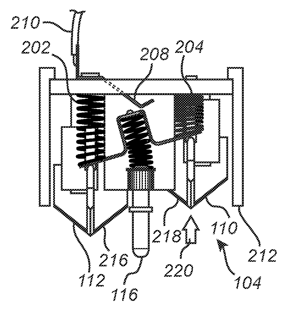
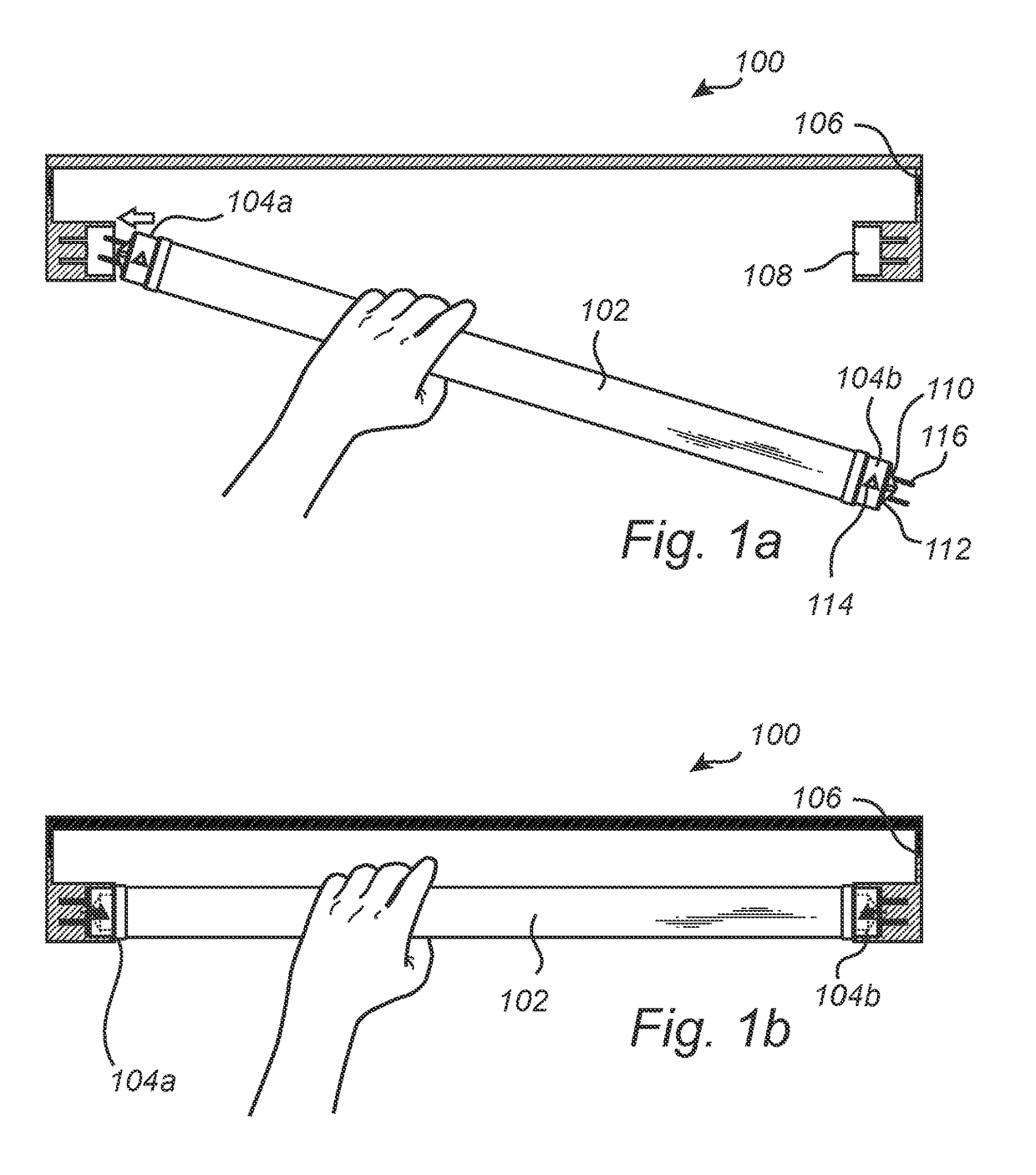
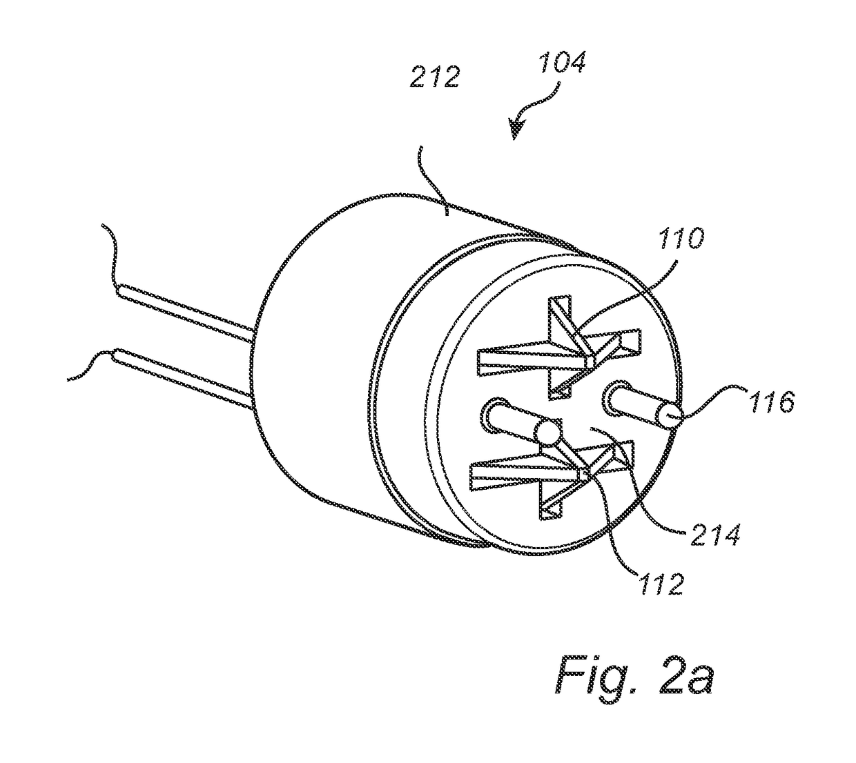
[0039]FIG. 1a schematically illustrates a luminaire 100 wherein a tubular light source 102 comprising two end caps 104a, 104b of the same sort according to an embodiment of the present invention is being mounted into a mains connected fixture 106. As illustrated in FIG. 1a, one end cap 104a is first inserted into a socket 108 arranged in the fixture 106, thereby depressing and actuating a first and a second spring loaded switching element 110, 112 arranged on the outside of the end cap 104a. In this state, when one end cap ...


PUM


Abstract

The present invention relates to an end cap (104) for a tubular light source the tubular light source configured to be arranged in a lighting fixture comprising a socket, wherein the end cap (104) comprises a housing portion having a connection end, two connector pins (116) at least partly arranged on an outside of the housing portion at the connection end, wherein the connector pins (116) are configured to fit in the sockets of the lighting fixture, a first spring loaded switching element (110) configured to be alternately positioned in an actuated state and a non-actuated state, wherein the first spring loaded switching element (110) protrudes at the connection end of the housing portion in the vicinity of the connector pins (116) when positioned in its non-actuated state, and a second spring loaded switching element (112) configured to be positioned in an actuated state and a non-actuated state, wherein the switching elements (110, 112) are configured to be individually positioned in their respective actuated states to form an electrical connection between the socket and the tubular light source when the end cap (104) is mounted into the socket of the fixture.

Description

CROSS-REFERENCE TO PRIOR APPLICATIONS[0001]This application is the U.S. National Phase application under 35 U.S.C. §371 of International Application No. PCT / IB2014 / 058082, filed on Jan. 7, 2014, which claims the benefit of U.S. Provisional Patent Application No. 61 / 756,240, filed on Jan. 24, 2013. These applications are hereby incorporated by reference herein.TECHNICAL FIELD[0002]The present invention relates to an end cap for a tubular light source, and in particular to an end cap enabling safe installation of such a tubular light source.BACKGROUND OF THE INVENTION[0003]Fluorescent lighting tubes are commonly used in a large range of lighting systems as a result of advantages such as longer life time and better luminous efficiency compared to incandescent lamps. However, in the continuous effort to reduce power consumption, it is desirable to replace conventional light tubes with still more energy efficient and environmental friendly alternatives. One such alternative is to use LED...

Claims


Application Information

Patent Timeline
Patent Type & Authority Patents(United States)
IPC IPC(8): F21V25/04H01R33/94F21V23/04F21K9/27H01R33/96F21V21/002F21K9/272H01R13/70F21V23/06F21Y103/10F21Y115/10
CPCH01R33/96F21K9/27F21K9/272F21V21/002F21V23/04F21V25/04H01R13/701H01R33/942F21V23/06F21Y2115/10F21Y2103/10
Inventor JANSEN, MARTIJN EVERT PAULWANG, HONGWUVERHOEVEN, MARK JOHANNES ANTONIUSZHOU, LIANGGIELEN, VINCENT STEFAN DAVIDBUKKEMS, PETER JOHANNES MARTINUSCALON, GEORGES MARIEDEN BOER, REINIER IMRE ANTONDE MOL, EUGEN JACOB
Owner SIGNIFY HLDG BV
Why Eureka
Try Eureka