
Sensor device

Active Publication Date: 2010-08-05
ROBERT BOSCH GMBH
View PDF3 Cites 31 Cited by
  • Summary
  • Abstract
  • Description
  • Claims
  • Application Information

AI Technical Summary

Benefits of technology

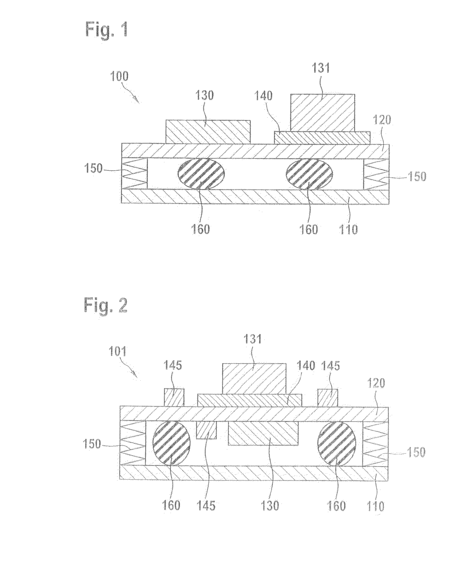
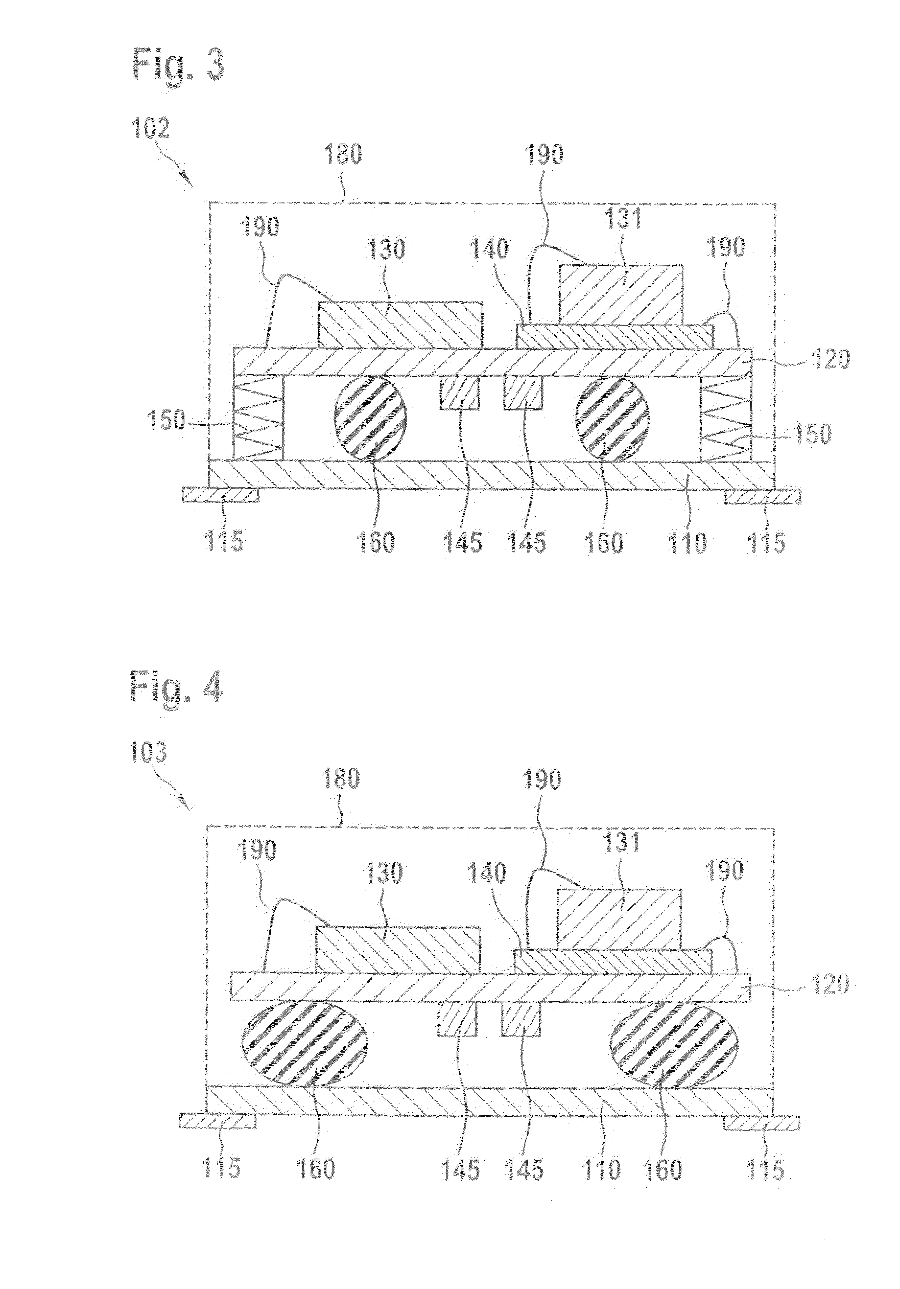
[0013]In another example embodiment, the spring / damper device has, in addition to the damper element, a first connecting element connected to the bearer part and a second connecting element connected to the housing base part. Here, the damper element surrounds the first connecting element and the second connecting element surrounds the damper element. In such a spring / damper device, it is possible for the bearer part and the housing base part not only to be elastically moved toward one another or away from one another, but also to be laterally displaced relative to one another, achieving a decoupling against impacts and vibrations in all spatial directions.
[0016]In addition, according to the present invention a housing is provided for a sensor device that has a housing base part, a bearer part for bearing a chip structure, and a spring / damper device via which the housing base part and the bearer part are connected elastically to one another. The housing is distinguished in that the housing base part, the spring / damper device, and the bearer part are situated one over the other, enabling a small (lateral) constructive size.

Problems solved by technology

A change in the operating frequency due to external influences causes impairment or falsification of the measurement.
However, the horizontal situation of the bearer part inside the housing base part entails a relatively large space requirement.
However, this design results in a low fall stability of the sensor device.
A deflection of the bearer part relative to the housing base part that occurs when there is an impact can cause a compression or plastic deformation of the bonding wires, resulting in contacts between the bonding wires and thus to undesired short-circuits in the operation of the sensor device.

Method used


Image

  • Sensor device
  • Sensor device
  • Sensor device

Examples


Embodiment Construction

[0021]The following description explains possible example embodiments of a sensor device according to the present invention, also referred to as a sensor module or a sensor package. Areas of application of the sensor devices include, for example, safety systems of motor vehicles, such as ESP (Electronic Stability Program). The sensor devices have an arrangement for spring suspension and damping in order to decouple a chip structure from external mechanical influences such as impacts or vibrations.

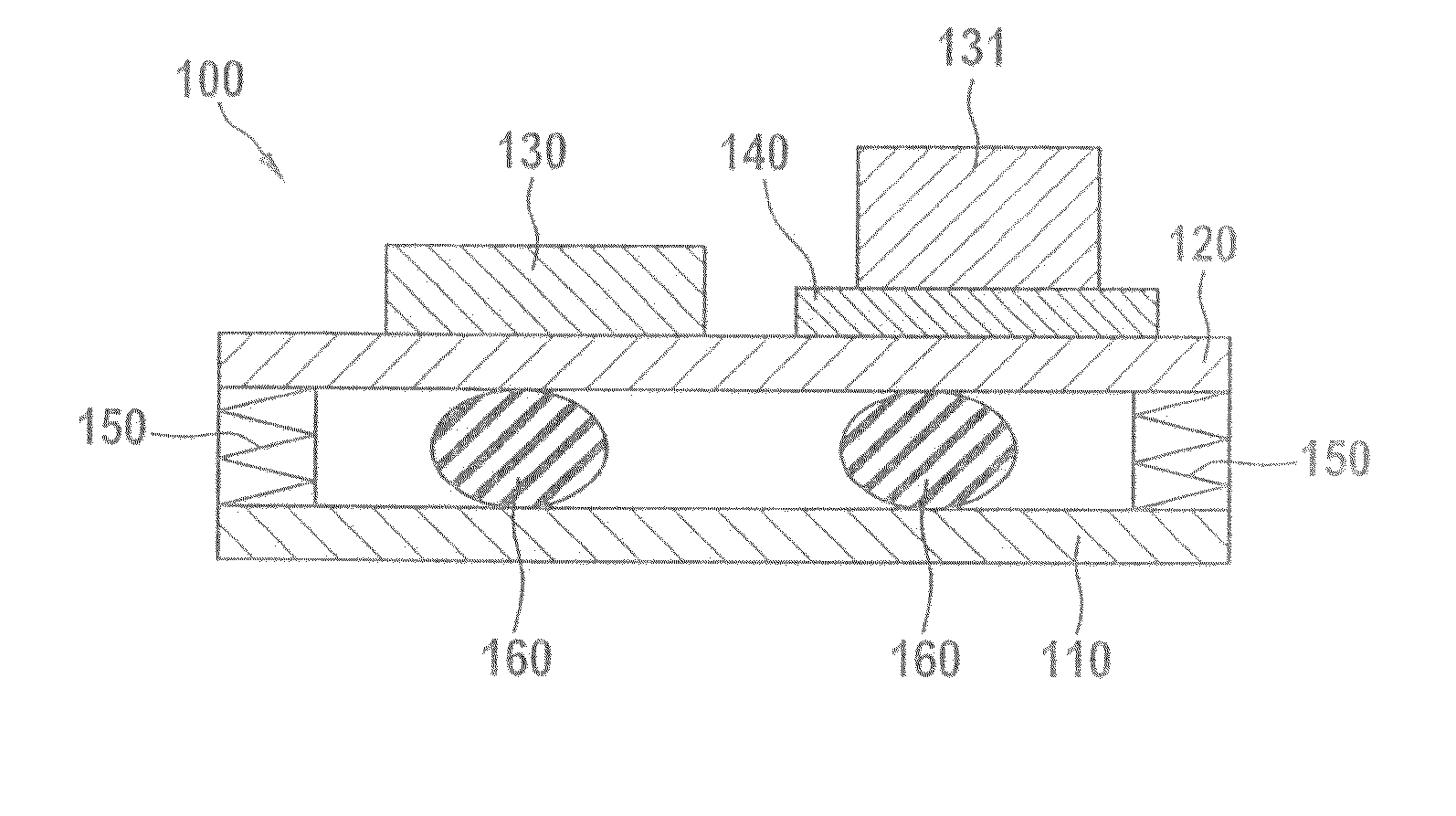
[0022]FIG. 1 shows a sensor device 100 in a schematic side view. Sensor device 100 has a plate-shaped bearer part 120 for bearing a chip structure, called bearer plate 120 hereinafter. The chip structure includes an evaluation chip 140 and two micromechanical sensor chips 130, 131, of which one is fashioned for example for the acquisition of an acceleration and the other is fashioned for the acquisition of a rate of rotation. Sensor chip 130 and evaluation chip 140 are situated next to one ...


PUM


Abstract

A sensor device includes a housing base part, a bearer part, a chip structure situated on the bearer part, and a spring / damper combination via which the housing base part and the bearer part are elastically connected to one another. In the sensor device, the housing base part, the spring / damper combination and the bearer part are situated one over the other.

Description

BACKGROUND OF THE INVENTION[0001]1. Field of the Invention[0002]The present invention relates to a sensor device having a housing base part, a bearer part, a chip structure situated on the bearer part, and a spring / damper device via which the housing base part and the bearer part are elastically connected to one another.[0003]2. Description of Related Art[0004]Sensor devices used for example in safety systems of motor vehicles standardly have a chip structure that has one or more sensor chips as well as an evaluation chip. The sensor chip is fashioned in the form of a micromechanical component (MEMS: Micro Electro Mechanical System) having movable functional elements in order to acquire a physical measured quantity, such as an acceleration or a rate of rotation. The evaluation chip is used to control the sensor chip, and for the evaluation or further processing of measurement signals of the sensor chip.[0005]A requirement of such sensor devices is that the sensor chips should be dec...

Claims


Application Information

Patent Timeline
IPC IPC(8): G01D11/10
CPCB81B7/0012B81B2201/025G01P1/023G01C19/56B81B2207/07H01L2224/48091B81B7/0016H01L2924/00014
Inventor ULM, MARKUSSTRUCHHOLZ, MICHAELJOBERT, TRISTANOFFTERDINGER, KLAUSKLAUS, THOMASGERHARDT, CHRISTIANGRABMAIER, FLORIANDITTMANN, DIRK
Owner ROBERT BOSCH GMBH
Learn More