Battery and holding structure for same

Inactive Publication Date: 2010-09-02
CHI MEI COMM SYST INC
View PDF4 Cites 10 Cited by
  • Summary
  • Abstract
  • Description
  • Claims
  • Application Information

AI Technical Summary

Problems solved by technology

However, a space between the battery and the sidewall of the receiving cavity is required for an assembly of the battery to the portable electronic device.

Method used


Image

  • Battery and holding structure for same
  • Battery and holding structure for same
  • Battery and holding structure for same

Examples


Embodiment Construction

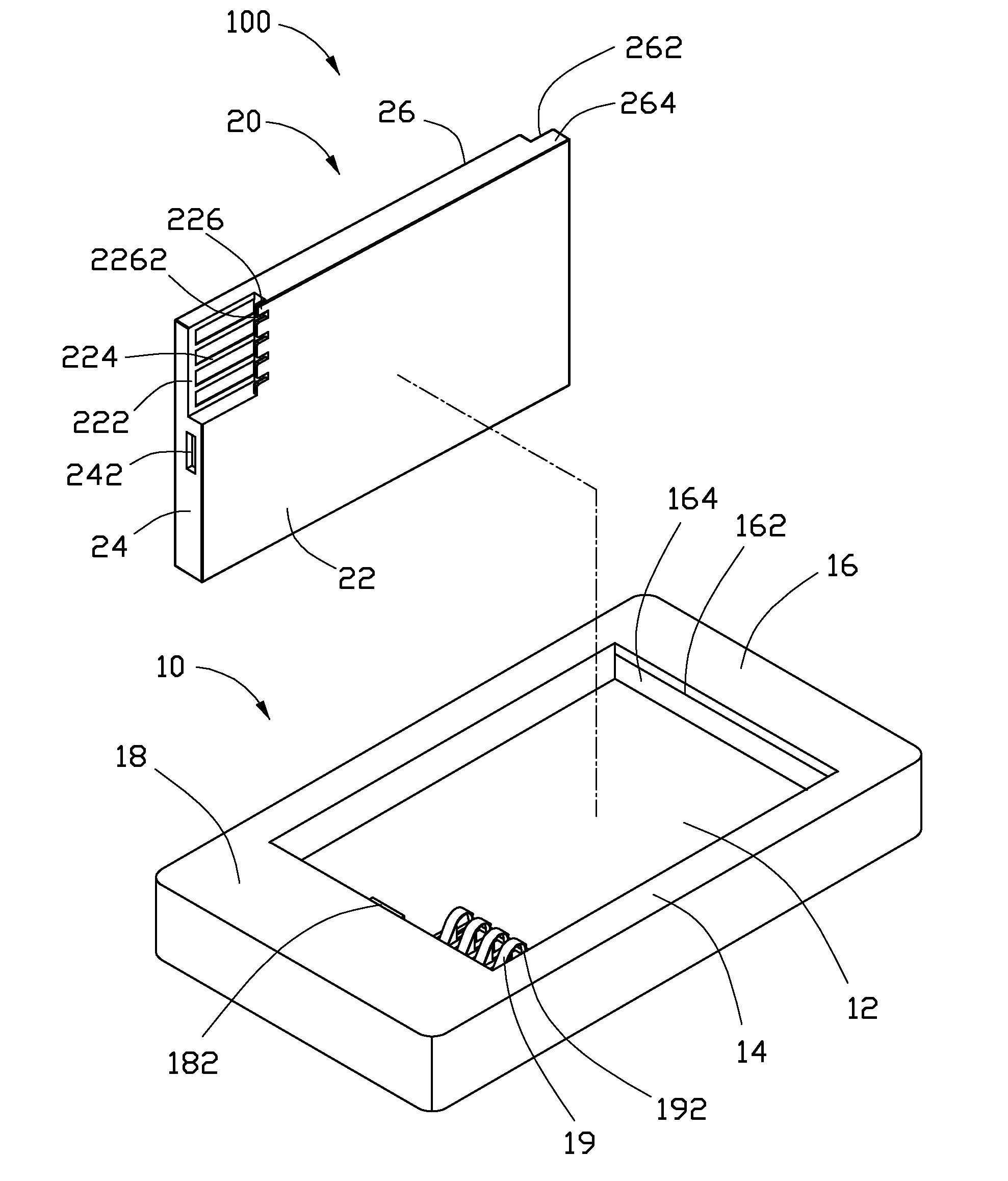
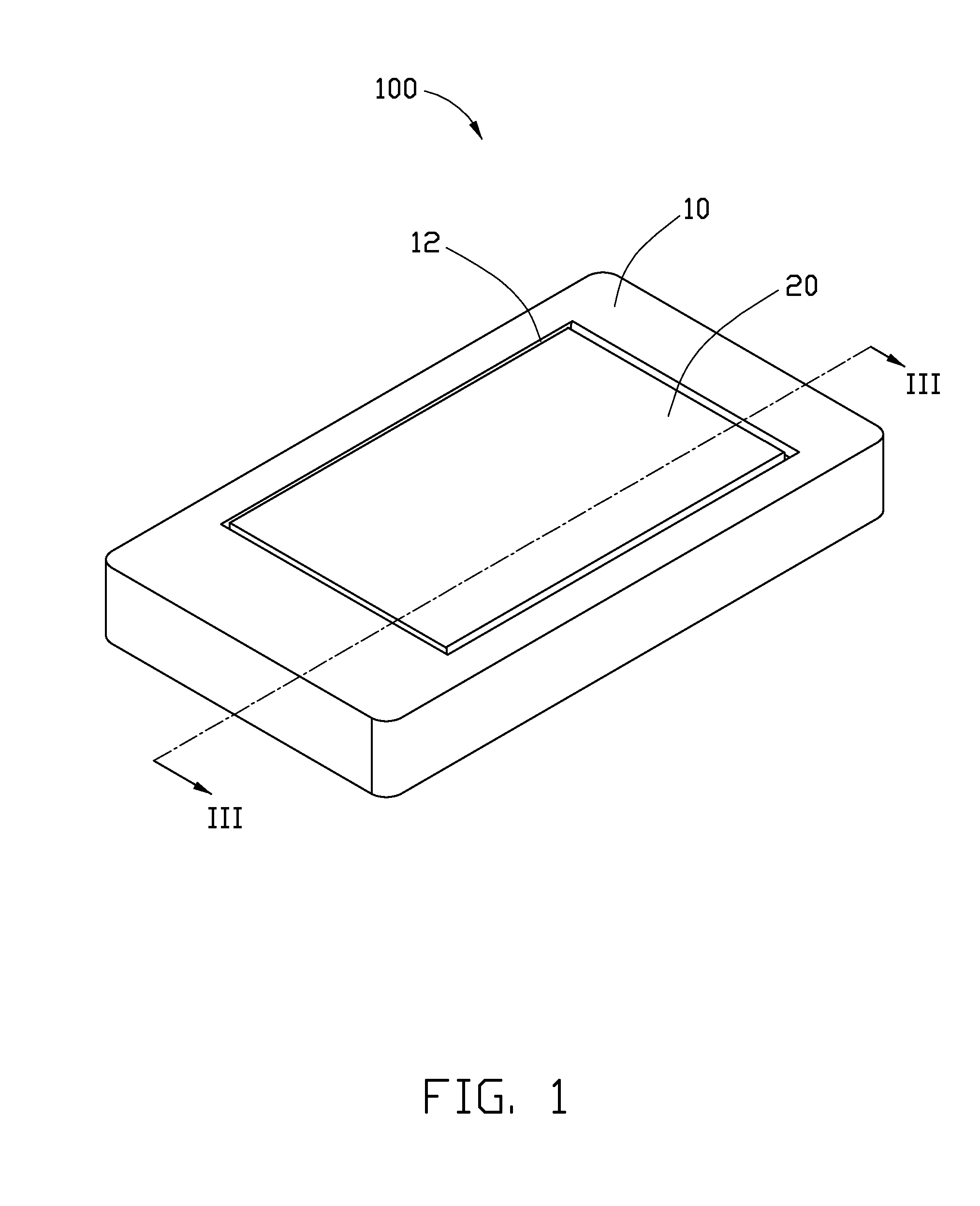
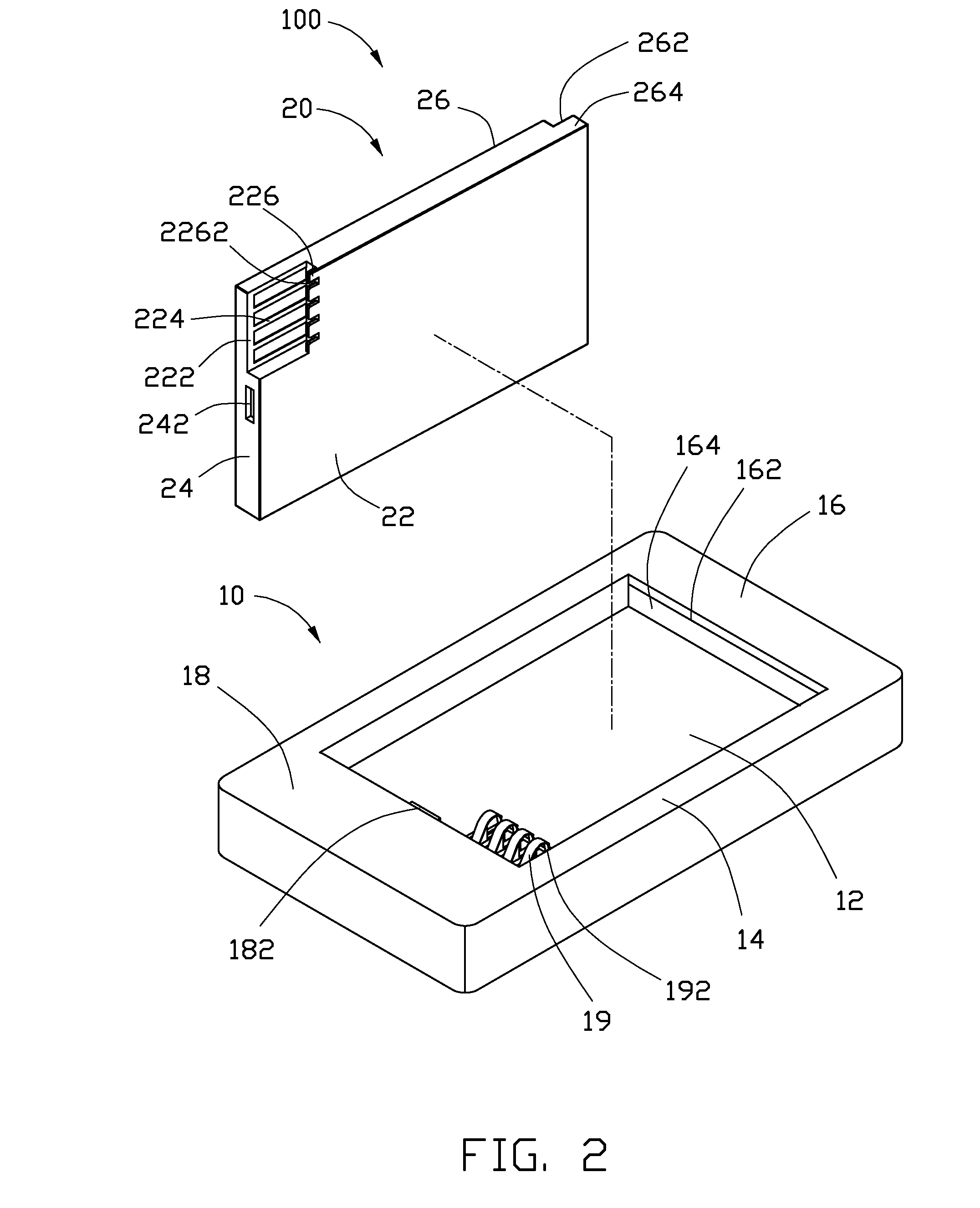
[0011]FIG.s 1 and 2 show an exemplary holding structure 100 for mobile phones, and other portable electronic devices, such as personal digital assistants (PDAs), digital cameras, etc. The holding structure 100 includes a housing 10 and a battery 20 detachably received in the housing 10.

[0012]The housing 10 defines a receiving cavity 12 to receive the battery 20. The receiving cavity 12 is enclosed by two sidewalls 14, a first end wall 16, and a second end wall 18. The first end wall 16 defines a locking groove 162 communicating the receiving cavity 12. The locking groove 162 is for latching with an end portion of the battery 20. The locking groove 162 has a stopping board 164 and an elastic member 166 (show in FIG. 3) therein. The elastic member 166 is resisted and deformed between the bottom of the locking groove 162 and the stopping board 164. The stopping board 164 can be moved within the locking groove 162 under the deformation of the elastic member 166. The second end wall 18 h...


PUM

PropertyMeasurementUnit
holding structureaaaaaaaaaa
widthaaaaaaaaaa
conductiveaaaaaaaaaa

Abstract

A holding structure comprises a housing and a battery, the housing defines a receiving cavity, an end wall of the receiving cavity forms a protrusion, the other end wall defines a locking groove, a plurality of elastic pins formed on the bottom of the receiving cavity. The battery has a latching hole defined on one end to receive the protrusion, the other end forms an engaging end to engage with the locking groove. Each of the elastic pins has a clamping section, the battery forms a plurality of latching slots, the clamping section latch into the latching slot correspondingly after the battery is received in the receiving cavity.

Description

BACKGROUND[0001]1. Field of the Disclosure[0002]The present disclosure relates to batteries and holding structures, particularly to a battery and a holding structure for holding the battery.[0003]2. Description of Related Art[0004]Portable electronic devices such as mobile phones and personal digital assistants (PDAs) are widely used. A battery having conductive connectors formed is generally installed in a receiving cavity of the portable electronic device. The conductive connector contact corresponding metallic elastic pins exposed inside the receiving cavity. Accordingly, the battery electrically connects the integrated circuit of the electronic device and provides electric energy for the electronic device. The battery is covered and secured by a cover.[0005]However, a space between the battery and the sidewall of the receiving cavity is required for an assembly of the battery to the portable electronic device. The battery may move within the receiving cavity due to the space. Du...

Claims


Application Information

Patent Timeline
Patent Type & Authority Applications(United States)
IPC IPC(8): H01M2/10H01M10/00H01M50/103H01M50/244H01M50/247H01M50/262H01M50/55
CPCH01M2/0207H01M2/0217H01M2/1066H04M1/0262H01M2/30H01M10/0436H01M2/20Y02E60/10H01M50/103H01M50/55
Inventor HUANG, CHIH-CHIEN
Owner CHI MEI COMM SYST INC
Why Eureka
Try Eureka