
System and method for the compression and quantitative measurement of movement from synchronous video

a synchronous video and quantitative measurement technology, applied in the field of computer software, can solve the problems of loss, inefficient use of typically expensive computing resources, and loss of most compression techniques, such as mpeg forma

Inactive Publication Date: 2006-07-04
CADWELL INDS
View PDF16 Cites 57 Cited by
  • Summary
  • Abstract
  • Description
  • Claims
  • Application Information

AI Technical Summary

Problems solved by technology

Requiring the testing facility to record and maintain the entire eight-hour synchronous video becomes resource depleting and an inefficient use of typically expensive computing resources, especially if this type of testing is repeated often and conducted on a large patient group.
One skilled in the relevant art will appreciate that most compression techniques, such as the MPEG format, are lossy in that the restored image is an imperfect copy of the original.
However, because a change in subsequent frames implies movement within the video image, the reduced frame resolution by the loss of detail information is typically unnoticeable (or at least acceptable) to the human eye.
Although conventional lossy video image compression formats, such as the MPEG video format, attempt to reduce the amount of data required to store and recreate synchronous video images, these conventional formats are not well suited for specific application to the detection and quantification of movement over extended periods of time while maintaining smaller sized data files.
Considering that a single patient generates approximately eight hours of data per test period, use of the MPEG format would quickly consume large quantities of testing facility processing and memory storage resources.
Moreover, the MPEG format does not provide any quantification or measurement of the amount of movement with the video image.

Method used


Image

  • System and method for the compression and quantitative measurement of movement from synchronous video
  • System and method for the compression and quantitative measurement of movement from synchronous video
  • System and method for the compression and quantitative measurement of movement from synchronous video

Examples


Embodiment Construction

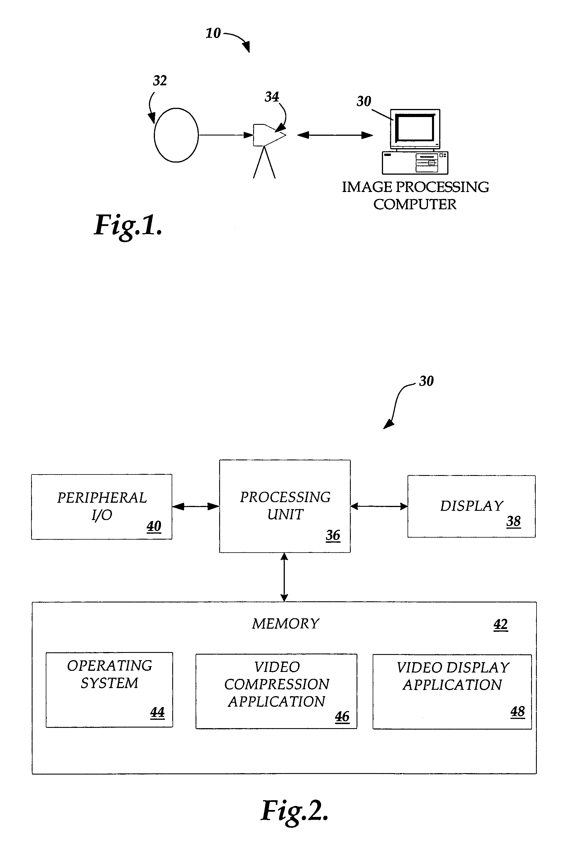
[0027]The present application is directed to a system and method for compressing and capturing movement from synchronous video. Specifically, the present invention will be described in relation to a computer system 10 for processing the synchronous video data. One skilled in the relevant art will appreciate that the system disclosed is illustrative in nature and should not be construed as limiting.

[0028]Referring now to FIG. 1, in an actual embodiment of the present invention, the system 10 is embodied in a stand-alone configuration including an image-processing computer 30. The image-processing computer 30 captures a video image 32 with a connected device, such as a video camera 34, and processes the image in accordance with the present invention. As illustrated in FIG. 1, the video camera 34 is directly connected to the image processing computer 30. One skilled in the relevant art will appreciate that the image-processing computer 30 may be connected to more than one video cameras...


PUM


Abstract

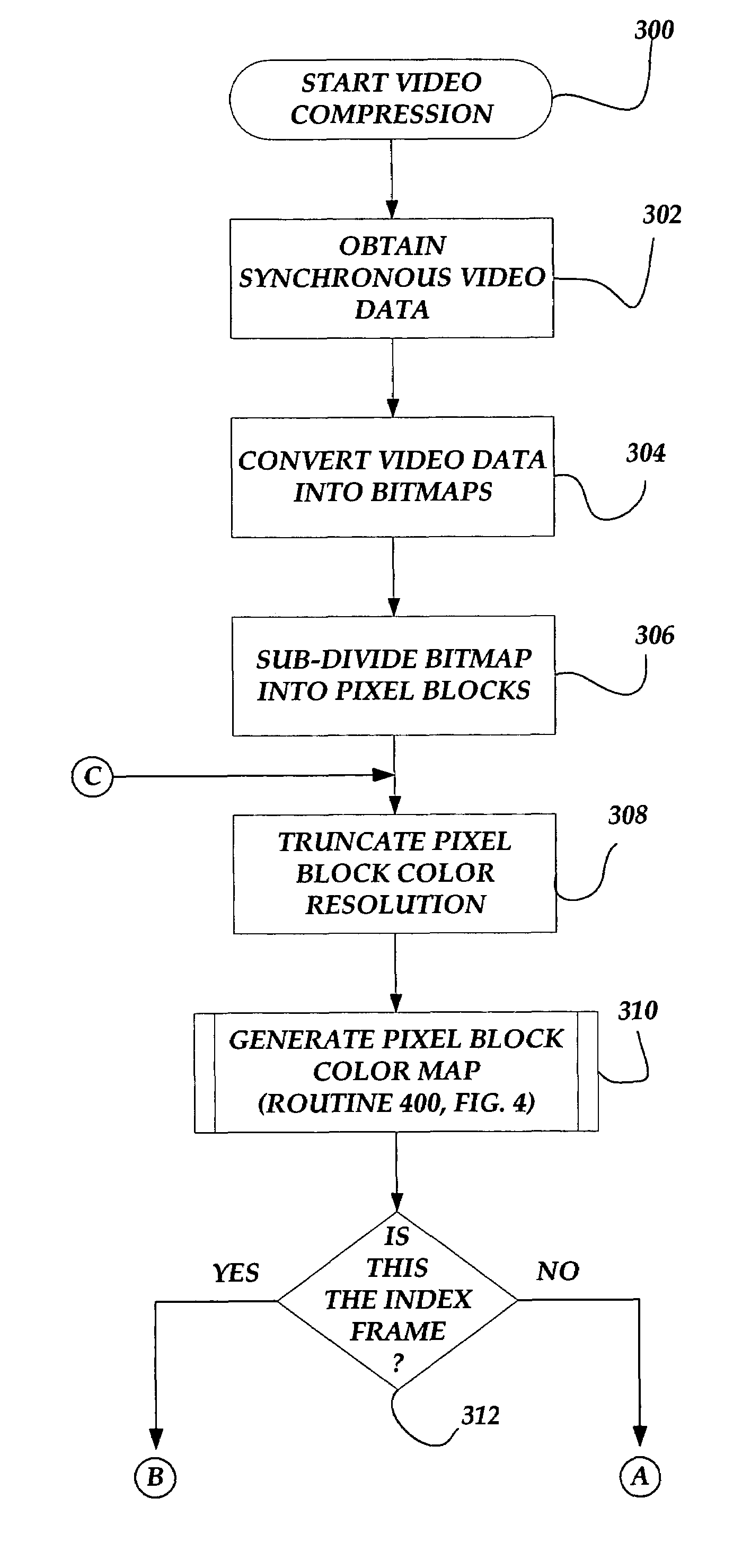
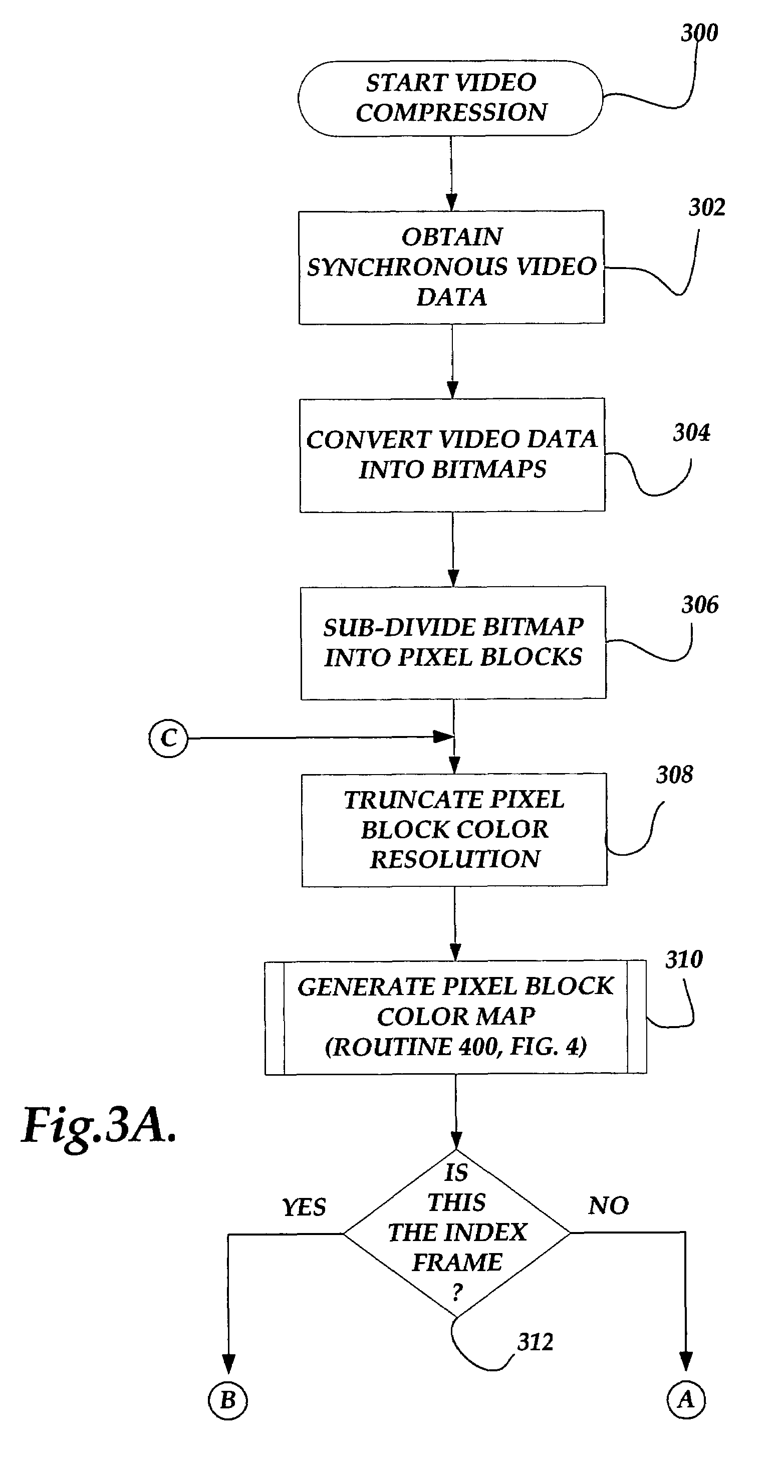
A system and method for optimizing and quantifying movement in synchronous video are provided. An image-processing computer obtains a synchronous video image, which is converted to color bitmap frames. Each frame is then sub-divided into smaller pixel blocks. Processed independently, the size of each pixel block is reduced by truncation of the color resolution and the use of a limited color table for the pixel block. The cumulative color difference in the pixel block is calculated and if it is below a threshold, the pixel block data will not be saved. Alternatively, the pixel block data is compressed and saved. Upon decoding, the color difference between each pixel and the same pixel in the preceding frame is compared. The color difference is assigned a pseudocolor and is displayed on the screen. Larger color differences are represented with more pronounced pseudocolors.

Description

CROSS-REFERENCE TO RELATED APPLICATION[0001]This application claims the benefit of U.S. Provisional Application No. 60 / 213,083, filed Jun. 19, 2000, which is hereby incorporated by reference.FIELD OF THE INVENTION[0002]The present application relates to computer software, and in particular, to a system and method for compressing and quantifying movement in synchronous video.BACKGROUND OF THE INVENTION[0003]The production and storage of images in synchronous digital video provide potential advantages over other ways of recording images, such as conventional analog video images stored on magnetic tape for display on television sets (e.g., VCR tape). For example, digital video images permit a user to scan and access specific time frames within the video with a minimal amount of access time. In conjunction with computing systems having suitable processing and storage facilities, the use of synchronous digital video becomes a practical medium for a variety of applications.[0004]One speci...

Claims


Application Information

Patent Timeline
Patent Type & Authority Patents(United States)
IPC IPC(8): G06K9/36
CPCH04N19/503H04N19/176H04N19/122H04N19/112H04N19/93H04N19/132H04N19/186H04N19/152H04N19/182H04N19/12
Inventor CADWELL, JOHN A.
Owner CADWELL INDS
Learn More