

Power transmission mechanism
a transmission mechanism and power technology, applied in the direction of couplings, fluid couplings, interengaging clutches, etc., can solve the problems of time-consuming surface treatment of these components, and achieve the effect of securely transmitting power without impacts and eliminating the need for high-level fabrication accuracy
- Summary
- Abstract
- Description
- Claims
- Application Information
AI Technical Summary
Benefits of technology
Problems solved by technology
Method used
Image

Examples
Embodiment Construction
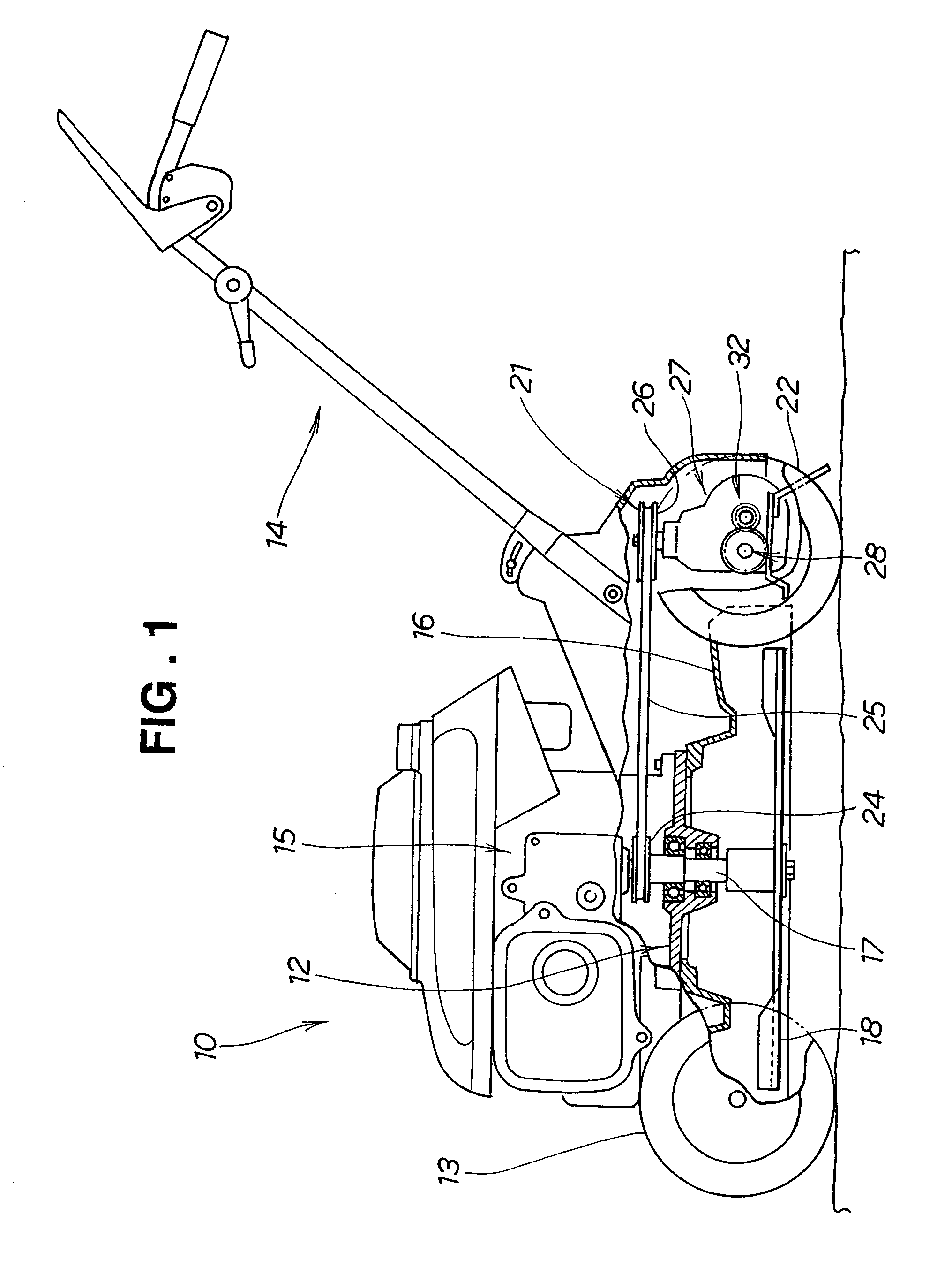
[0027]For the description of the present embodiment, a lawn mower will be exemplarily illustrated as an embodiment employing power transmission mechanisms according to the present invention.
[0028]A lawn mower 10 shown in FIG. 1 is a walk-behind self-propelled lawn mower with which an operator mows, walking behind the lawn mower 10.
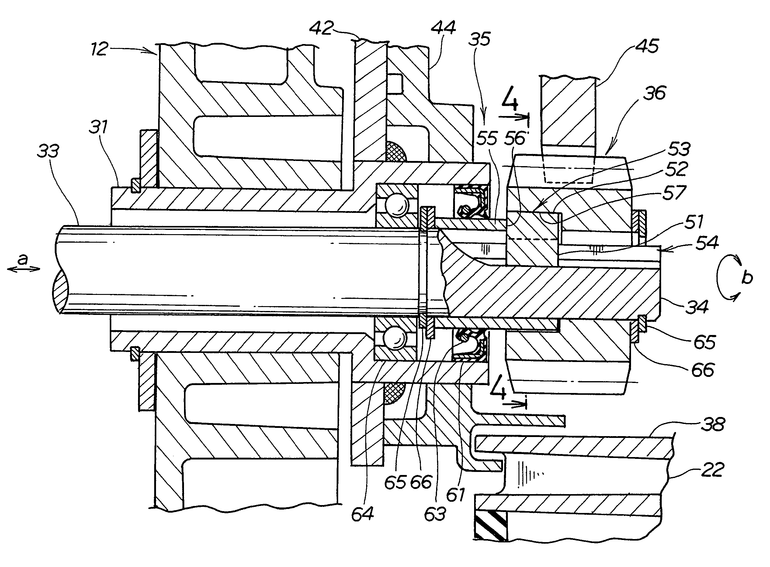
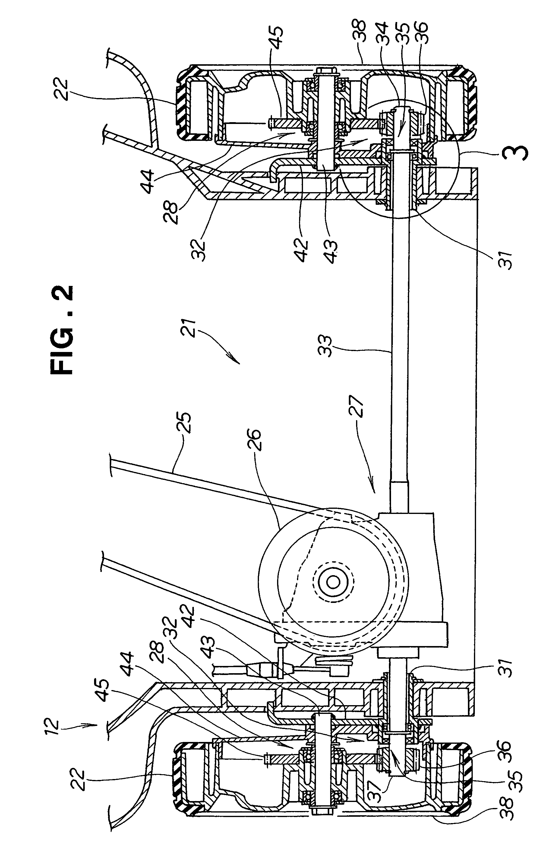
[0029]The lawn mower 10 includes a body frame 12, right and left front wheels 13 mounted to the body frame 12 (the right front wheel 13 is not shown because FIG. 1 is a view of the lawn mower 10 taken from one side), an engine 15 mounted on an upper middle portion of the body frame 12, a cutting blade 18 connected to an output shaft 17 of the engine 15, a drive unit 21 connected to the output shaft 17, and right and left drive wheels 22 as rear wheels connected to the drive unit 21 (only the left rear wheel 22 is shown as described with the front wheels 13).
[0030]An operating handle 14 extends obliquely from the rear of the body frame 12 in a rearward and ...
PUM
 Abstract
Description
Claims
Application Information