Fuel inlet structure for personal watercraft

a technology for fuel inlet structures and watercraft, which is applied in the direction of special purpose vessels, vessel parts, containers preventing decay, etc., can solve the problems of shortening the life of the chain, affecting the use of the protective tube, and sometimes affecting the fuel filling tube or the member around the deck. , to achieve the effect of expanding the utility of the protective tub

Inactive Publication Date: 2006-07-11
HONDA MOTOR CO LTD
View PDF15 Cites 12 Cited by
  • Summary
  • Abstract
  • Description
  • Claims
  • Application Information

AI Technical Summary

Benefits of technology

[0019]Alternatively, the stopper may be provided in the form of a slit washer which can be attached to the chain subsequent to initial assembly. Where the stopper is formed as a slit washer which can be attached to the chain subsequent to initial assembly, it is possible, for example, to slide a plurality of protective tubes onto the chain, and attach the protective tubes at an arbitrary position of the chain with a slit washer later. As a result, expansion of the utility of the protective tube can be realized.

Problems solved by technology

With the known fuel filler structure for a personal watercraft described above, when the fill cap is suspended on the fuel fill tube by the chain, the chain sometimes impacts on the fuel fill tube or on a member around the deck and damages the fuel filler or the deck.
Further, when the chain impacts on the fuel filler or a member around the deck, the chain itself may be damaged, which shortens the life of the chain.

Method used


Image

  • Fuel inlet structure for personal watercraft
  • Fuel inlet structure for personal watercraft
  • Fuel inlet structure for personal watercraft

Examples


first embodiment

[0040]FIG. 3 is an exploded perspective view of the fuel filler structure for a personal watercraft and shows major parts of the fuel filler structure 60.

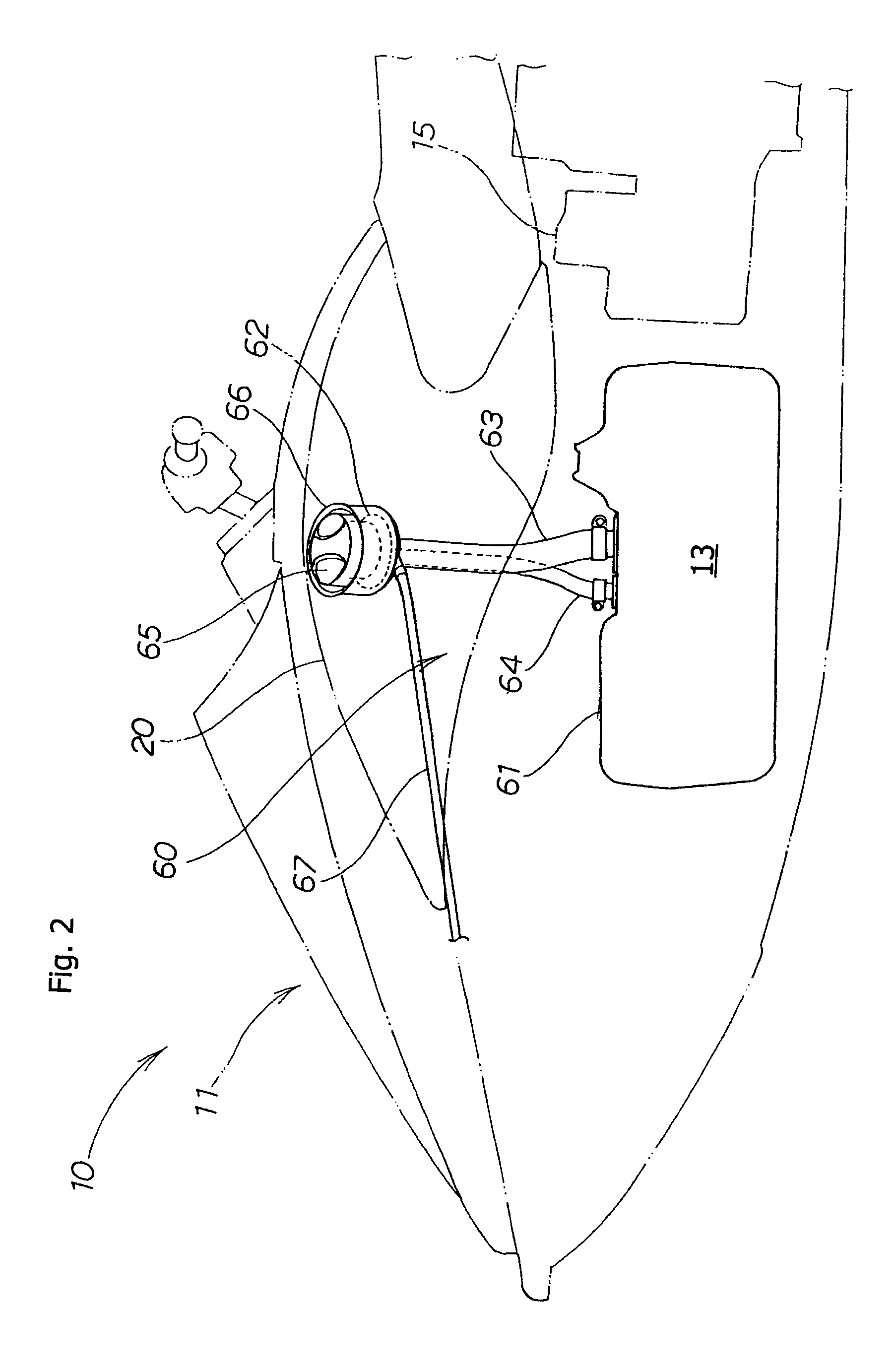
[0041]The fuel tank 13 is a tank formed from a fuel tolerant plastic resin, and includes an upper surface 61 (FIG. 2) with an inlet port 61a to which the fuel supply hose 63 is connected, and a connecting port 61b to which the bleed hose 64 is connected. A fuel pump 75 is provided inserted in an opening 61c formed in the upper surface 61 of the fuel tank 13, and a securing ring 76 is provided surrounding the opening 61c, for securing the fuel pump 75 therein.

[0042]A first hose band 63a is provided for securing an upper end of the fuel supply hose 63 around the bottom of the fuel fill neck 62, as well a second hose band 63b for securing the lower end of the fuel supply hose 63 to the inlet port 61a.

[0043]A third hose band 64a is provided for securing an upper end of the bleed hose 64 to the fuel fill neck 62, and a fourth hose ban...

second embodiment

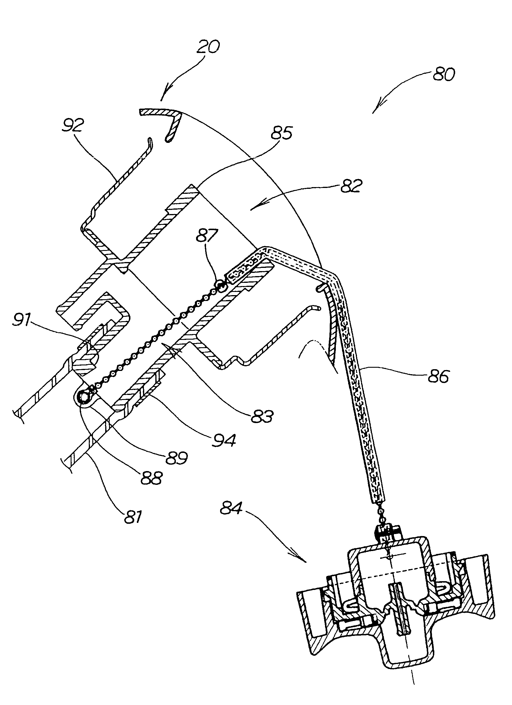
[0065]The fuel filler structure 80 for a personal watercraft, is configured such that in a fuel filler structure for a small size craft of the type wherein a fuel tank 13 is disposed in a craft body 11 (FIG. 1) and a fuel supply hose 81 extends from the fuel tank 13 with an end thereof connected to a fuel filler member 82 on a deck 20 while one end of a chain 83 is fastened to the inside of the fuel filler member 82 and the other end of the chain 83 is connected to a fill cap 84, the chain 83 includes a protective tube 86 as a sleeve surrounding the chain 83, at a location where the chain 83 contacts the fuel filler 85 when the fill cap 84 is removed.

[0066]In FIG. 7, reference numeral 87 denotes a bead attached to an intermediate portion of the chain 83. The bead 87 serves as a stopper for stopping movement of the protective tube 86. A washer 88 is attached to an end of the chain 83, for connecting the chain to a fastening portion 89 formed on the fill tube.

[0067]Also in the embodi...


PUM

PropertyMeasurementUnit
workabilityaaaaaaaaaa
rotationaaaaaaaaaa
pressureaaaaaaaaaa

Abstract

A fuel inlet apparatus is provided for a personal watercraft of the type having a fuel tank 13 disposed in a craft body 11, and a fuel supply hose 81 extending from the fuel tank 13 with an end thereof connected to a fuel filler member 82 on a deck 20. One end of a chain 83 is fastened inside the fuel filler member 82, and the other end of the chain 83 is fastened to a fill cap 84 used for sealably closing the top of the fuel filler member 82. The chain 83 has a protective tube 86 surrounding a portion thereof, to contact the fuel filler 85 when the fill cap 84 is removed. The provision of the protective tube 86 reduces the risk of damage to the fuel filler or the deck, and the chain itself can also be protected by the tube.

Description

CROSS-REFERENCE TO RELATED APPLICATIONS[0001]The present application claims priority under 35 U.S.C. 119, based on Japanese patent application No. 2002-266074, filed Sep. 11, 2002.BACKGROUND OF THE INVENTION[0002]1. Field of the Invention[0003]The present invention relates to a fuel inlet structure for a personal watercraft. More particularly, the present invention relates to a fuel inlet structure including a fuel fill tube, with a fuel filler cap restrained by of a chain interconnecting the fuel filler cap and the fuel fill tube, to prevent loss of the fuel filler cap or damage to the personal watercraft during fuel filling service.[0004]2. Description of the Background Art[0005]One fuel inlet structure for a personal watercraft is known wherein a chain is attached to a fuel fill tube, and connects the fill tube to a cap provided for closing up an open end of the fuel fill tube. For example, Japanese Laid-Open Patent No. 2000-53091 has this type of connection.[0006]FIG. 9 of the p...

Claims


Application Information

Patent Timeline
Patent Type & Authority Patents(United States)
IPC IPC(8): B65D55/16B63H11/08B63B25/08B63B35/73B63H21/38F02M37/00
CPCB63B25/082B63B35/731B63B2770/00B63H21/38B63B34/10
Inventor ABE, TOMOHISANODA, YOSHIAKI
Owner HONDA MOTOR CO LTD
Why Eureka
Try Eureka