
Filter cleaning device of cyclone vacuum cleaner

Inactive Publication Date: 2006-07-11
SAMSUNG GWANGJU ELECTRONICS CO LTD
View PDF4 Cites 34 Cited by
  • Summary
  • Abstract
  • Description
  • Claims
  • Application Information

AI Technical Summary

Benefits of technology

[0013]The present invention has been developed in order to solve the above problems in the related art. Accordingly, an aspect of the present invention is to provide a filter cleaning device of a simplified construction but with improved durability, which can easily and cleanly remove minute dust particles collected on an outer surface of a filter disposed in a cyclone type dust collecting apparatus.
[0014]Another aspect of the present invention is to provide a filter assembly for a cyclone type dust collecting apparatus which has a simplified construction, requiring reduced amount of manufacturing cost, and is easy to assemble and disassemble.
[0019]It is preferred that the manipulation unit and the filter are respectively provided with spring fixing portions for securely positioning the elastic spring.

Problems solved by technology

However, because minute dust particles are gradually accumulated on an outer surface of the filter, there is an inconvenience in that the filter has to be cleaned periodically.
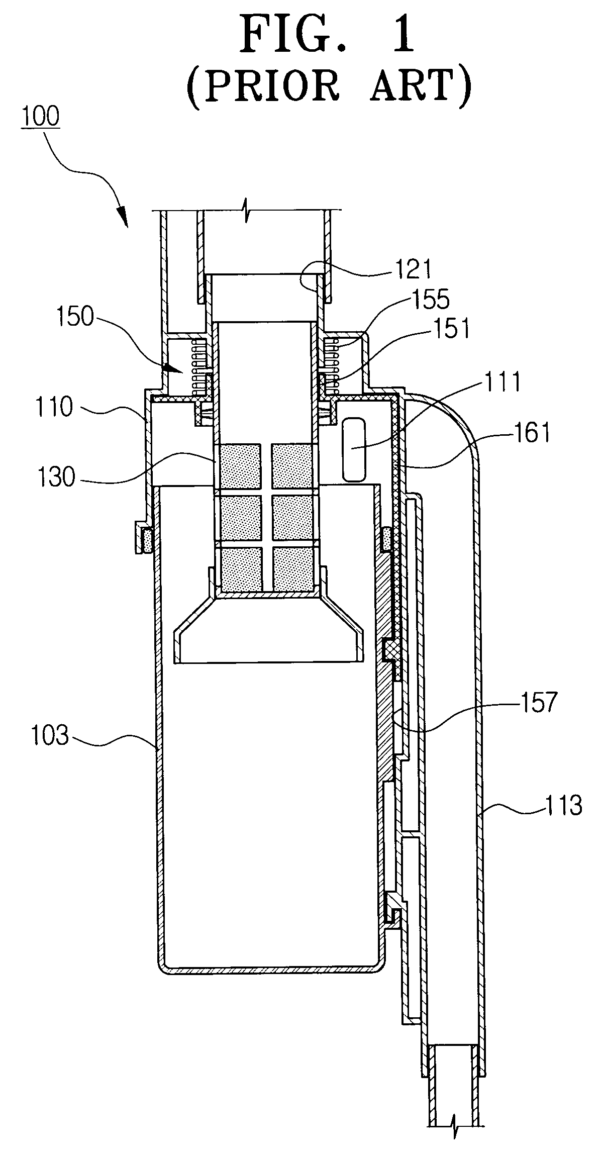
Further, the guide recess 157 between the cyclone body 110 and the dust collecting receptacle 103 which guides the sliding of the slider 161 and also receives the locking lever 171 for manipulation by the user, makes manufacturing difficult, and causes manufacturing costs to increase.
Also, the filter cleaning device 100 is inconvenient to use since it is uneasy to separate / connect the dust-collecting receptacle 103 from / to the cyclone body 110.
Especially, when excessive force is exerted on the manipulation knob 209, the manipulation knob 209 is likely to be damaged.

Method used


Image

  • Filter cleaning device of cyclone vacuum cleaner
  • Filter cleaning device of cyclone vacuum cleaner
  • Filter cleaning device of cyclone vacuum cleaner

Examples


Embodiment Construction

[0028]Hereinafter, the present invention will be described in greater detail with reference to the accompanying drawings.

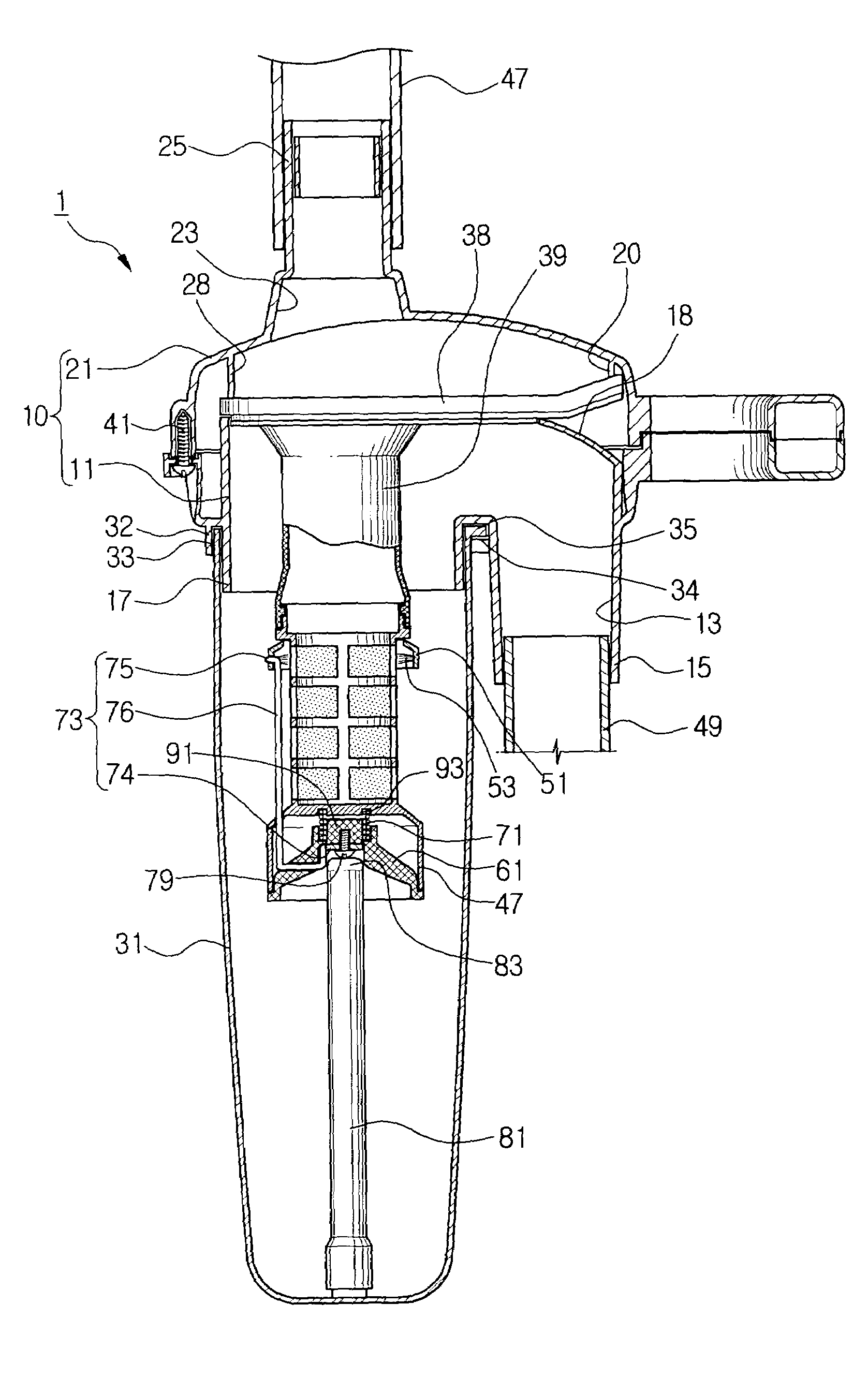
[0029]FIG. 4 is a cross-section view partially showing a cyclone type dust collecting apparatus where a filter cleaning device according to the present embodiment is mounted. As shown in FIG. 4, a cyclone type dust collecting apparatus 1 includes a cyclone body 10 having a suction port 13 and a discharge port 23, a dust collecting receptacle 31 removably mounted on the cyclone body 10, a filter 40 installed at the discharge port 23 of the cyclone body 10 and disposed inside the dust collecting receptacle 31, and a filter cleaning device 50 for removing dust collected on an outer surface of the filter 40.

[0030]The cyclone body 10 is comprised of an upper body 21 wherein the discharge port 23 is disposed, and a lower body 11 wherein the suction port 13 is disposed. The upper and the lower bodies 21, 11 are secured to each other by a plurality of screws 41. A connect...


PUM

PropertyMeasurementUnit
Forceaaaaaaaaaa
Elasticityaaaaaaaaaa

Abstract

A filter cleaning device for a cyclone vacuum cleaner which comprises a cyclone body having a suction port and a discharge port, a dust collecting receptacle connected to the cyclone body for collecting dusts separated from air drawn in through the suction port, and a filter connected to the discharge port and disposed inside the dust collecting receptacle. The filter cleaning device includes a manipulation unit disposed under the filter to approach to, and retreat from the filter. A connection member is interposed between the manipulation unit and the dust-removing ring for moving the dust-removing ring in association with the approaching and retreating movements of the manipulation unit. An elastic spring is interposed between the filter and the manipulation unit for urging the manipulation unit to retreat from the filter.

Description

FIELD OF THE INVENTION[0001]The present invention relates generally to a cyclone type dust collecting apparatus of a vacuum cleaner, and more particularly, to a device for cleaning a filter disposed in a cyclone dust collecting apparatus to filter out minute dust particles from the air after large particles of dust have been separated from the air by a centrifugal force.BACKGROUND OF THE INVENTION[0002]A filter disposed in a cyclone type dust collecting apparatus of a vacuum cleaner generally filters out minute dust particles from air as air is discharged toward a cleaner body. However, because minute dust particles are gradually accumulated on an outer surface of the filter, there is an inconvenience in that the filter has to be cleaned periodically. Accordingly, various filter cleaning devices have been suggested to remove the dust from the outer surface of the filter in association with opening and closing motion of a dust collecting receptacle of the cyclone type dust collecting...

Claims


Application Information

Patent Timeline
IPC IPC(8): B01D45/12B04C5/185A47L9/20B01D46/42B01D50/00
CPCA47L9/20Y10S55/03B01D46/681B01D50/00
Inventor JIN, HYOUNG-JONGOH, JANG-KEUN
Owner SAMSUNG GWANGJU ELECTRONICS CO LTD
Learn More