Radar altimeter having an automatically calibrated sensitivity range control function

a technology of automatic calibration and altimeter, applied in the field of radar altimeter, can solve the problems of reduced performance, difficult processing of ground return signal at low altitude, for example, during landing and take-off operations, and the general performance of radar altimeter at very low altitud

Inactive Publication Date: 2006-07-11
HONEYWELL INT INC
View PDF17 Cites 14 Cited by
  • Summary
  • Abstract
  • Description
  • Claims
  • Application Information

AI Technical Summary

Problems solved by technology

However, radar altimeters typically provide marginal performance at very low altitudes, for example, during landing and take-off.
The reduction in performance is partially due to interfering signals resulting from a leakage path between the transmit and receive antennas of the radar altimeter.
As described above, the ground return signal at low altitudes, for example, during landing and take-off operations, is difficult to process.
The difficulty is partially caused by the leakage path signals.

Method used


Image

  • Radar altimeter having an automatically calibrated sensitivity range control function
  • Radar altimeter having an automatically calibrated sensitivity range control function
  • Radar altimeter having an automatically calibrated sensitivity range control function

Examples


Embodiment Construction

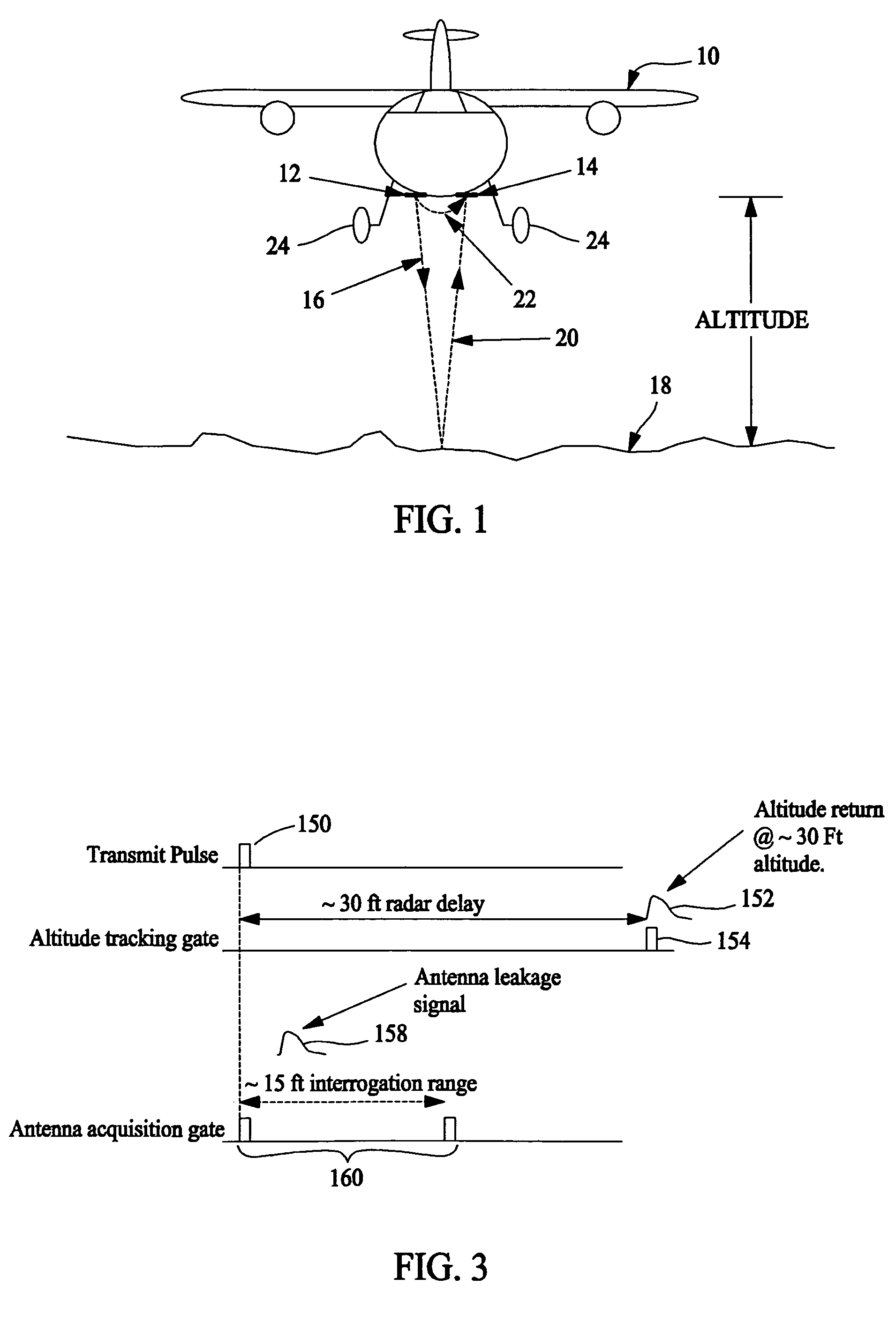
[0012]FIG. 1 is a diagram illustrating radar altimeter transmissions and returns with respect to an aircraft 10. Aircraft 10 is configured with a radar altimeter (not shown) which includes a transmit antenna 12 and a receive antenna 14 which are separated by a distance across a portion of the fuselage of aircraft 10. For radar altimeter operation, a transmit beam 16 is transmitted by transmit antenna 12, reflected by ground 18 (sometimes referred to as a terrain), and reflected beam 20 is received at receive antenna 14 for processing. A time between transmission from transmit antenna 12 to reception by receive antenna 14 is directly proportional to an altitude above ground 18. As described above, a leakage path 22 exists between transmit antenna 12 and receive antenna 14. A number of factors contribute to the characteristics of leakage path 22, some of which are described above. With reference to FIG. 1, a location of landing gears 24 with respect to transmit antenna 12 and receive ...


PUM


Abstract

A radar altimeter for an air vehicle is described. The radar altimeter includes a transmit antenna configured to transmit radar signals toward the ground, a receive antenna configured to receive radar signals reflected from the ground, the receive antenna also receiving signals propagated along a leakage path from the transmit antenna, and a receiver configured to receive signals from the receive antenna. The radar altimeter also includes at least one altitude processing channel configured to receive signals from the receiver to determine an altitude, and an automatic sensitivity-range-control (SRC) channel configured to receive signals from the receiver. The SRC channel is configured to determine an amplitude of the received leakage path signals when an altitude of the radar altimeter is sufficient to separate received signals reflected from the ground from signals received from the leakage path.

Description

BACKGROUND OF THE INVENTION[0001]This invention relates generally to radar altimeter operations and more specifically, to a radar altimeter which includes an automatically calibrated sensitivity range control (SRC) function.[0002]A radar altimeter typically includes a transmitter for applying pulses of electromagnetic energy, at a radio frequency (RF), and at regular intervals to a transmit antenna which then radiates the energy, in the form of a transmit beam, towards the earth's surface. A transmit beam from a radar is sometimes said to “illuminate” an area (e.g. the ground) which reflects (returns) the transmit beam. The reflected beam, sometimes referred to as a ground return, is received at a receive antenna of the radar altimeter. A signal from the receive antenna is processed to determine an altitude of the aircraft incorporating the radar altimeter.[0003]However, radar altimeters typically provide marginal performance at very low altitudes, for example, during landing and ta...

Claims


Application Information

Patent Timeline
Patent Type & Authority Patents(United States)
IPC IPC(8): G01S13/08
CPCG01S7/34G01S13/882G01S7/4021
Inventor HAGER, JAMES R.SHOEMAKER, MARK S.JORGENSEN, THOMAS J.
Owner HONEYWELL INT INC
Why Eureka
Try Eureka