Image processing apparatus

a technology of image processing and image processing method, applied in the direction of geometric image transformation, image analysis, instruments, etc., can solve the problems of image unnatural, image unnatural, image joining utilizing the weighted mean processing becomes unnatural at the region, etc., and achieves the effect of preventing image degradation

a technology of image processing and image processing method, applied in the direction of geometric image transformation, image analysis, instruments, etc., can solve the problems of image unnatural, image unnatural, image joining utilizing the weighted mean processing becomes unnatural at the region, etc., and achieves the effect of preventing image degradation

US7076116B2Inactive Publication Date: 2006-07-11MINOLTA CO LTD

Image

  • Image processing apparatus
  • Image processing apparatus
  • Image processing apparatus

Examples


first embodiment

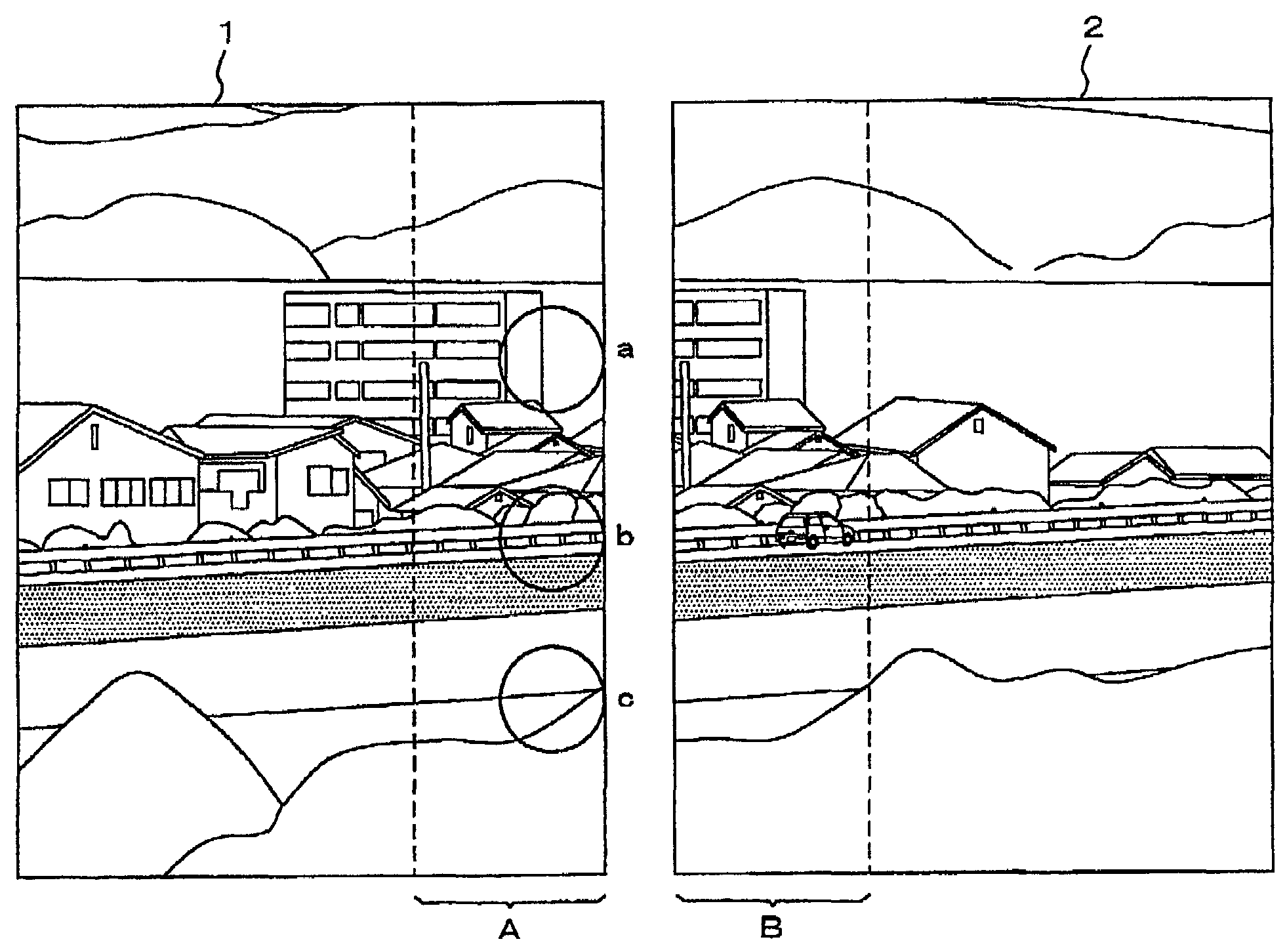
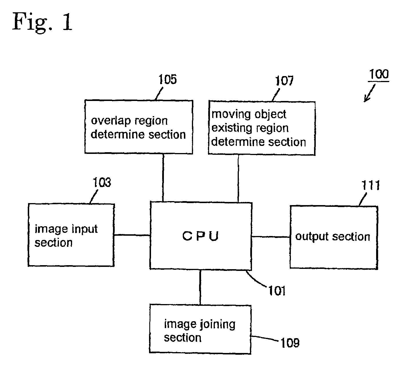
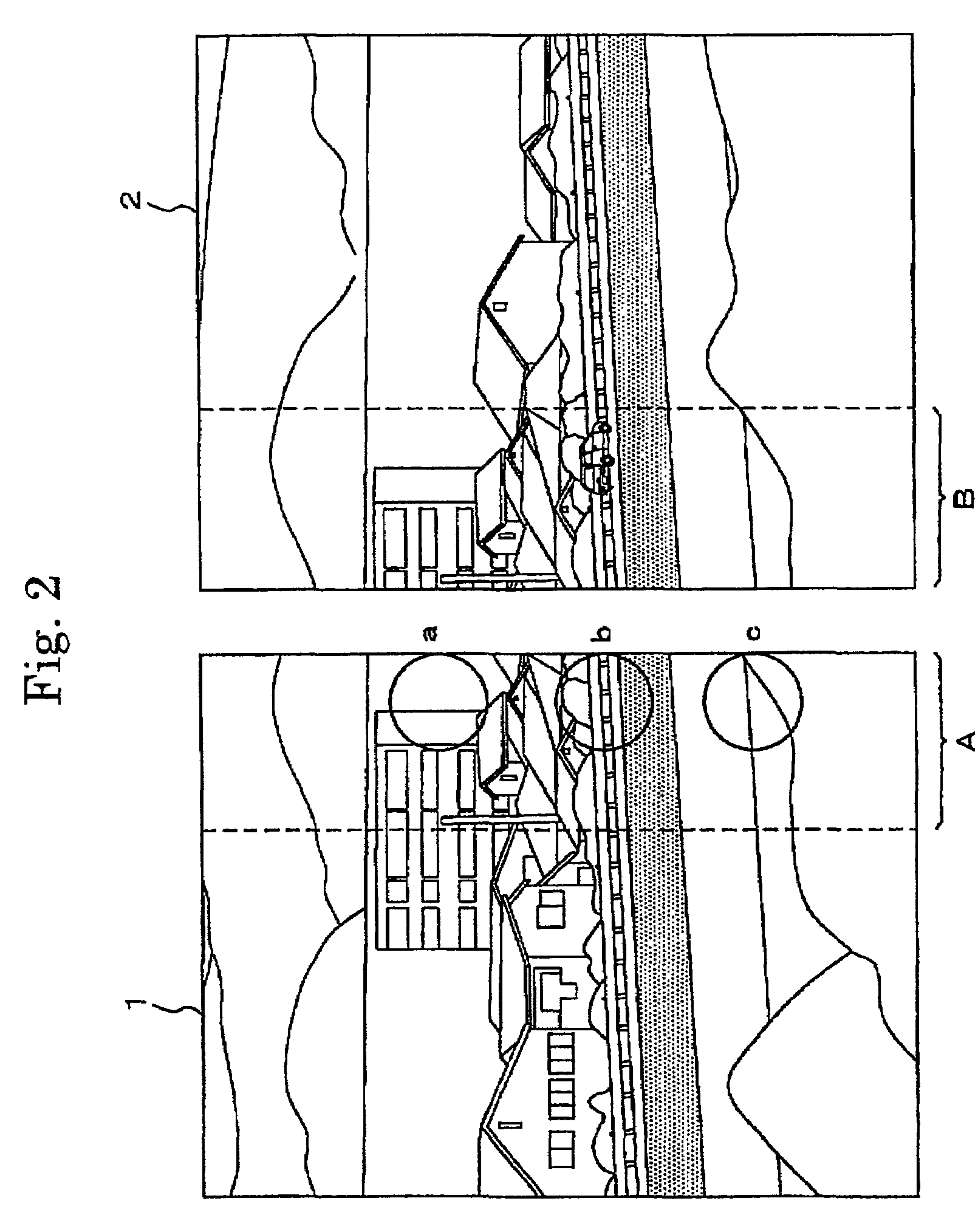
[0057]FIG. 1 is a block diagram showing a schematic structure of an image processing apparatus 100 according to a first embodiment of the present invention. The image processing apparatus 100 comprises a CPU (Central Processing Unit) 101 for overall controlling of the apparatus, an image input section 103 for inputting a plurality of captured images, an overlap region determining section 105 for determining an overlap region where adjacent ones of the inputted images overlap with each other, an moving object existing region determining section 107 for determining a region where a moving object exists in the overlap region determined, an image joining section 109 for joining the inputted images by determining a pixel value in the overlap region and a pixel value in a region other than the overlap region, and an output section 111 for outputting the joined image.

[0058]The image input section 103 inputs, to the image processing apparatus 100, a plurality of digital images captured by a...

second embodiment

[0118]Finally, an image processing apparatus 200 according to a second embodiment of the present invention will be described. The image processing apparatus 200 of this embodiment is identical in overall structure to the image processing apparatus 100 of the first embodiment shown in FIG. 1. Further, the flow of the image joining processing is the same as that shown in the flow chart of FIG. 6. In this embodiment, however, the content of the step for determining pixel values of the overlap region (Step S607) is slightly different.

[0119]FIG. 19 is a flow chart showing details of the process step for determining pixel values of the overlap region (Step S607 of FIG. 6) in the image processing apparatus 200 according to the second embodiment of the present invention. Although this flow chart is generally identical to the flow chart of FIG. 12, the criterion for determining which image of pixel value is to be used for the moving object existing region. Specifically, in this figure, inste...


PUM


Abstract

An image processing apparatus comprising image capturing means for capturing a plurality of images, adjacent ones of which partially overlap with each other, overlap region determining means for determining an overlap region, first region determining means for determining a first region within the overlap region determined, first pixel value determining means for determining a pixel value in the first region based on a pixel value of one of the two adjacent images, second pixel value determining means for determining a pixel value in a second region within the overlap region based on respective pixel values of the two adjacent images, and image joining means for joining the two adjacent images with each other by utilizing the determined pixel value in the first region and the determined pixel value in the second region as pixel values in respective regions of the overlap region.

Description

[0001]This application is based on application No. 2001-5245 filed in Japan, the content of which is hereby incorporated by reference.FIELD OF THE INVENTION[0002]The present invention relates to an image processing apparatus, an image processing method and image processing program which are capable of preventing image degradation in joining a plurality of images with each other to provide a single image even when there is a region where the contents of the images differ largely from each other. The invention also relates to a computer-readable recording medium storing the image processing program.DESCRIPTION OF THE RELATED ART[0003]As disclosed in the gazette of JP-A-9-330396, an image joining technique is known in which a plurality of images including a region where the images overlap with each other (hereinafter referred to as “overlap region”) are joined to provide a single image. This technique is effectively utilized for joining a plurality of separately captured images to obta...

Claims


Application Information

Patent Timeline
11 Jul 2006
Publication
US7076116B2
IPC
G06K9/36; G06T7/00; G06T3/00; G06T7/60; H04N1/387
CPC
G06T7/0024; G06T2200/32; G06T7/30
Inventors
HORIE, DAISAKU