
Lens-fitted photo film unit and printing method

a technology of lens-fitting photo film and printing method, which is applied in the direction of magnification glasses, instruments, camera body details, etc., can solve the problems of high manufacturing cost and inability to provide magnetic or optical recording devices in the lens-fitted photo film unit, and achieve the effect of easy confirmation of the orientation of the photographed imag

Inactive Publication Date: 2006-07-11
FUJIFILM CORP +1
View PDF11 Cites 4 Cited by
  • Summary
  • Abstract
  • Description
  • Claims
  • Application Information

AI Technical Summary

Benefits of technology

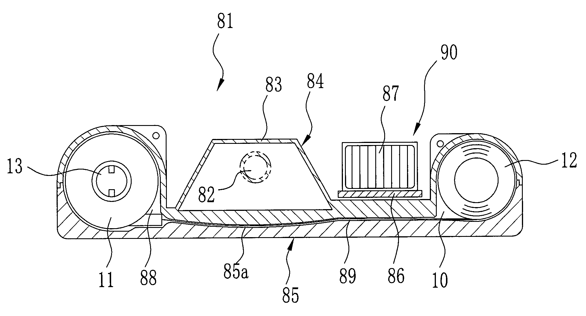
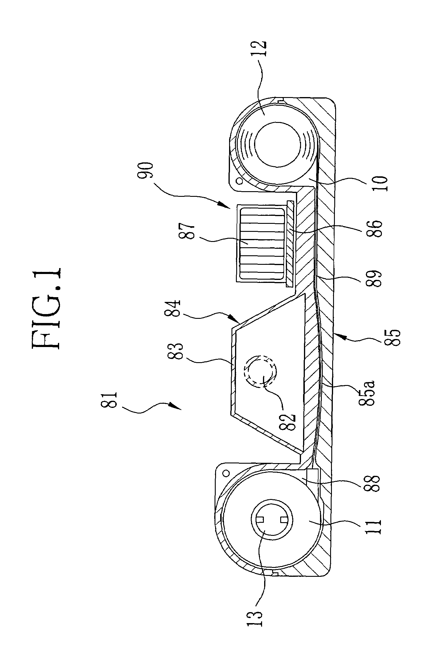
[0009]An object of the present invention is to provide a lens-fitted photo film unit at low cost which is provided with a photographic optical system having a mirror to realize miniaturization, and can certainly prevent reverse printing.
[0010]Another object of the present invention is to provide a printing method which is properly applicable to printing an image photographed with the above lens-fitted photo film unit.
[0017]According to the present invention, since the orientation of the photographed image is the same as that of the side print, confirming the orientation of the side print makes it possible to easily confirm the orientation of the photographed image. Accordingly, it is possible to subject the photo film, used in the lens-fitted photo film unit according to the present invention, to a developing process together with a photo film used in an ordinary camera.

Problems solved by technology

Thus, when an ordinary photo film is used in the mirror-equipped photographic optical system, there is a problem that a printing error such as reverse printing occurs because the photographed image in the photo film is flipped with respect to the side print.
To solve this problem, it is considerable to process the photo film used in the mirror-equipped photographic optical system separately from that used in a conventional photographic optical system, but it is troublesome.
In terms of reducing the manufacture cost, however, it is impossible to provide a magnetic or optical recording device in the lens-fitted photo film unit.

Method used


Image

  • Lens-fitted photo film unit and printing method
  • Lens-fitted photo film unit and printing method
  • Lens-fitted photo film unit and printing method

Examples


first embodiment

[0072]Referring to FIG. 10, the viewfinder 51 comprises a negative meniscus lens L11 as the objective lens element, a biconvex lens L12 as the first eyepiece lens element, and a positive meniscus lens L13 as the second eyepiece lens element. The focal length of the objective lens element L11, the first eyepiece lens element L12, and the second eyepiece lens element L13 is denoted as F11, F12, and F13, respectively. The values of F11 to F13 are as follows:

F11=−15.77 mm

F12=41.88 mm

F13=203.33 mm

[0073]Table 3 shows lens data of the viewfinder 51. The same abbreviations as Table 1 are used in Table 3.

[0074]

TABLE 3RCASRIDPFirst Surface56.3141.601.58529.9Second Surface*7.84316.93Third Surface65.1592.761.58529.9Fourth Surface*−38.65422.11Fifth Surface−19.2381.601.58529.9Sixth Surface*−17.068

[0075]In Table 3, Radius of Curvature (RC) and Air Space (AS) are expressed in millimeter (mm). Refractive Index (RI) and Dispersive Power (DP) are obtained with respect to D line (the wavelength is 587....

second embodiment

[0081]Referring to FIG. 11, the viewfinder 52 comprises a negative meniscus lens L21 as the objective lens element, a biconvex lens L22 as the first eyepiece lens element, and a negative meniscus lens L23 as the second eyepiece lens element. The focal length of the objective lens element L21, the first eyepiece lens element L22, and the second eyepiece lens element L23 is denoted as F21, F22, and F23, respectively. The values of F21 to F23 are as follows:

F21=−16.35 mm

F22=38.198 mm

F23=−500.34 mm

Accordingly, the refractive power of the first eyepiece lens element L22 is larger than the absolute value of the refractive power of the second eyepiece lens element L23.

[0082]Table 5 shows lens data of the viewfinder 52, and Table 6 shows aspheric coefficients.

[0083]

TABLE 5RCASRIDPFirst Surface88.6921.601.58529.9Second Surface*8.57622.95Third Surface2619.5683.001.58529.9Fourth Surface*−22.52915.85Fifth Surface−19.7951.601.58529.9Sixth Surface*−21.865

[0084]

TABLE 6Second SurfaceFourth SurfaceS...

third embodiment

[0087]Referring to FIG. 12, the viewfinder 53 comprises a negative meniscus lens L31 as the objective lens element, a positive meniscus lens L32 as the first eyepiece lens element, and a negative meniscus lens L33 as the second eyepiece lens element. The focal length of the objective lens element L31, the first eyepiece lens element L32, and the second eyepiece lens element L33 is denoted as F31, F32, and F33, respectively. The values of F31 to F33 are as follows:

F31=−16.79 mm

F32=36.63 mm

F33=−200.00 mm

Accordingly, the refractive power of the first eyepiece lens element L32 is larger than the absolute value of the refractive power of the second eyepiece lens element L33. Table 7 shows lens data of the viewfinder 53, and Table 8 shows aspheric coefficients.

[0088]

TABLE 7RCASRIDPFirst Surface72.9021.601.58529.9Second Surface*8.59025.49Third Surface−2386.2483.001.58529.9Fourth Surface*−21.24913.31Fifth Surface−25.2391.601.58529.9Sixth Surface*−32.934

[0089]

TABLE 8Second SurfaceFourth Surf...


PUM

PropertyMeasurementUnit
sizeaaaaaaaaaa
wavelengthaaaaaaaaaa
sizeaaaaaaaaaa

Abstract

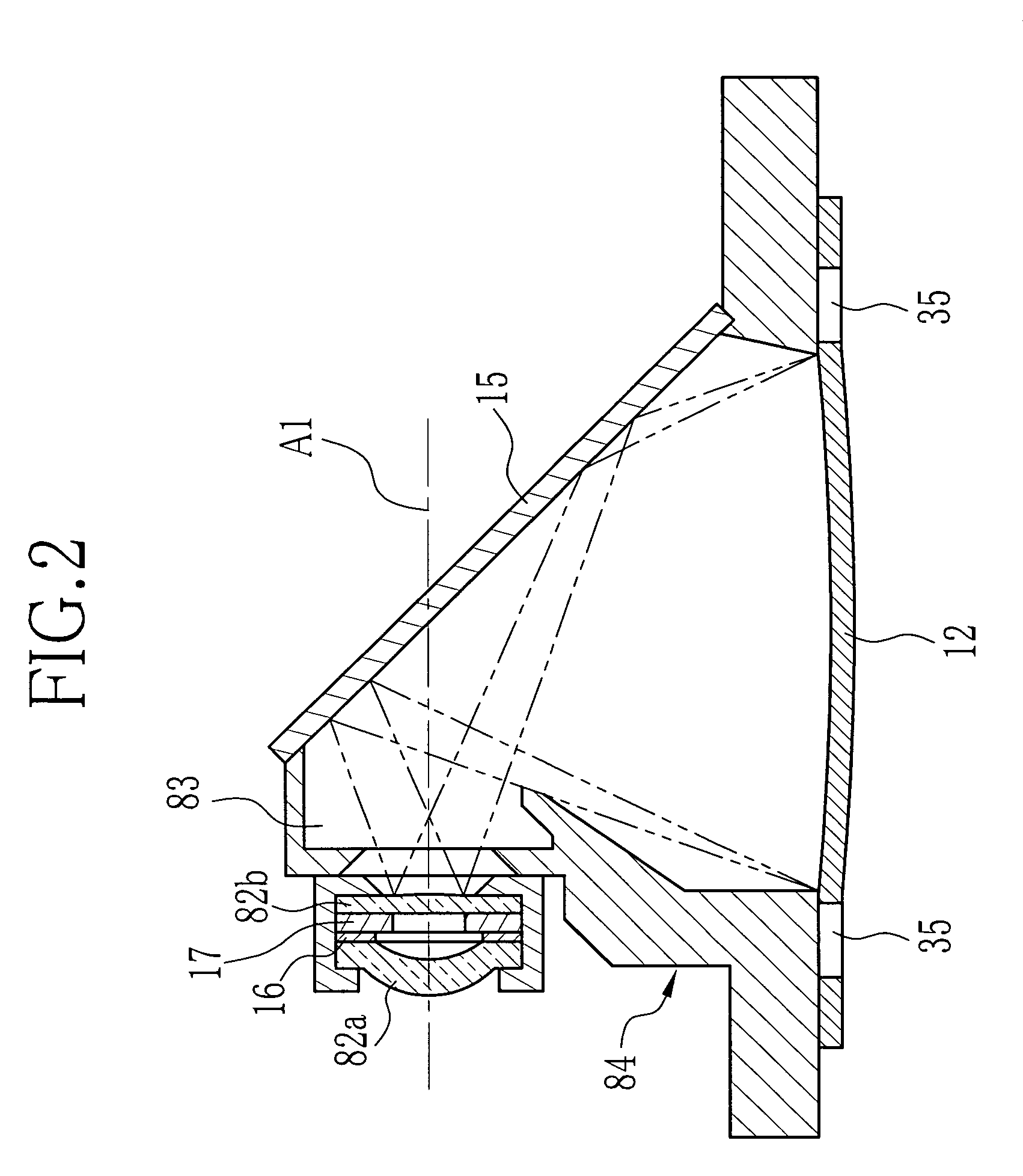
A lens-fitted photo film unit comprises a main body, a bottom lid, and a photo film. The main body has an exposure chamber with a taking lens. The exposure chamber is provided with a plane mirror disposed in such a manner as to be inclined 45 degrees with respect to the optical axis of the taking lens. Since the plane mirror reflects light from a subject, a photographic optical path of the light is perpendicularly bent. Subject light forms an image on the photo film disposed in parallel with the optical axis. A side print is exposed in the manufacture on the lateral edge of the photo film. Since the orientation of the photographed image is the same as that of the side print, it is possible to easily confirm the orientation of the photographed image in the development and print processes.

Description

BACKGROUND OF THE INVENTION[0001]1. Field of the Invention[0002]The present invention relates to a lens-fitted photo film unit having a plane mirror for bending a photographic optical path, and a method for printing an image photographed with this lens-fitted photo film unit.[0003]2. Background Arts[0004]A well-known lens-fitted photo film unit is preloaded with an unexposed photo filmstrip. The lens-fitted photo film unit is widely used because of its low price and facility to take a photograph with easy operations just after purchase. The lens-fitted photo film unit has been miniaturized in recent years. Using an APS film cartridge the size of which is smaller than a 35 mm film cartridge, for example, makes it possible to reduce the size of a cartridge chamber and an exposure area, so that a unit body becomes thin.[0005]In the conventional lens-fitted photo film unit, the photo filmstrip is disposed in such a manner as to be orthogonal to the optical axis of a taking lens. Accordi...

Claims


Application Information

Patent Timeline
Patent Type & Authority Patents(United States)
IPC IPC(8): G03B17/02G03B13/06G03B15/03G03B17/24G02B13/00G02B25/00G03B15/05G03B17/04G03B17/17G03B17/20G03B19/04G03C3/00
CPCG03B19/04G03B2219/045
Inventor KOIKE, KAZUMI
Owner FUJIFILM CORP
Learn More