Environmental scanning probe microscope

Inactive Publication Date: 2006-07-18
BRUKER NANO INC
View PDF13 Cites 10 Cited by
  • Summary
  • Abstract
  • Description
  • Claims
  • Application Information

AI Technical Summary

Benefits of technology

[0025]According to still a further aspect of the preferred embodiment, the AFM can be operated in a manner that is capable of initially determining whether the sample to be scanned is positioned on a plane parallel to the scan plane of the cantilever. If the sample is not positioned parallel to the probe, the AFM can automatically adjust the position of the sample utilizing the Z actuators connected to the stage assembly disposed within the superstructure to tilt the stage assembly on which the sample is positioned such that the sample

Problems solved by technology

A limiting factor to the more extensive use of the AFM was the inability to change the environmental conditions in which a particular sample positioned within the AFM is analyzed.
However, because most AFMs are constructed to be utilized only at ambient temperatures and pressures, such AFMs are not sealed as environmental conditions experienced by the sample do need to be altered from the ambient.
Although attempts have been made to offer environmental capability, there are significant drawbacks associated with performing tests under varying environmental conditions with existing AFMs.
However, due to the imperfect seal created between the cover and the chamber, it is difficult to obtain stable variations in the environment surrounding the sample.
Further, because the seal between the cover and the instruments and chamber is not hermetic, the seal can only withstand a certain pressure differential before failure, such that very low pressure environmental conditions, such as a vacuum, cannot be established within the AFM environment.
However, the construction of these types of AFMs makes it highly difficult to either change or alter the position of a sample being analyzed within the AFM that is undergoing analysis, such as to measure different selected areas of the sample surface or to compensate for sample drift.
Thus, much time and effort is exhausted in simply duplicating the environmental conditions

Method used


Image

  • Environmental scanning probe microscope
  • Environmental scanning probe microscope
  • Environmental scanning probe microscope

Examples


Embodiment Construction

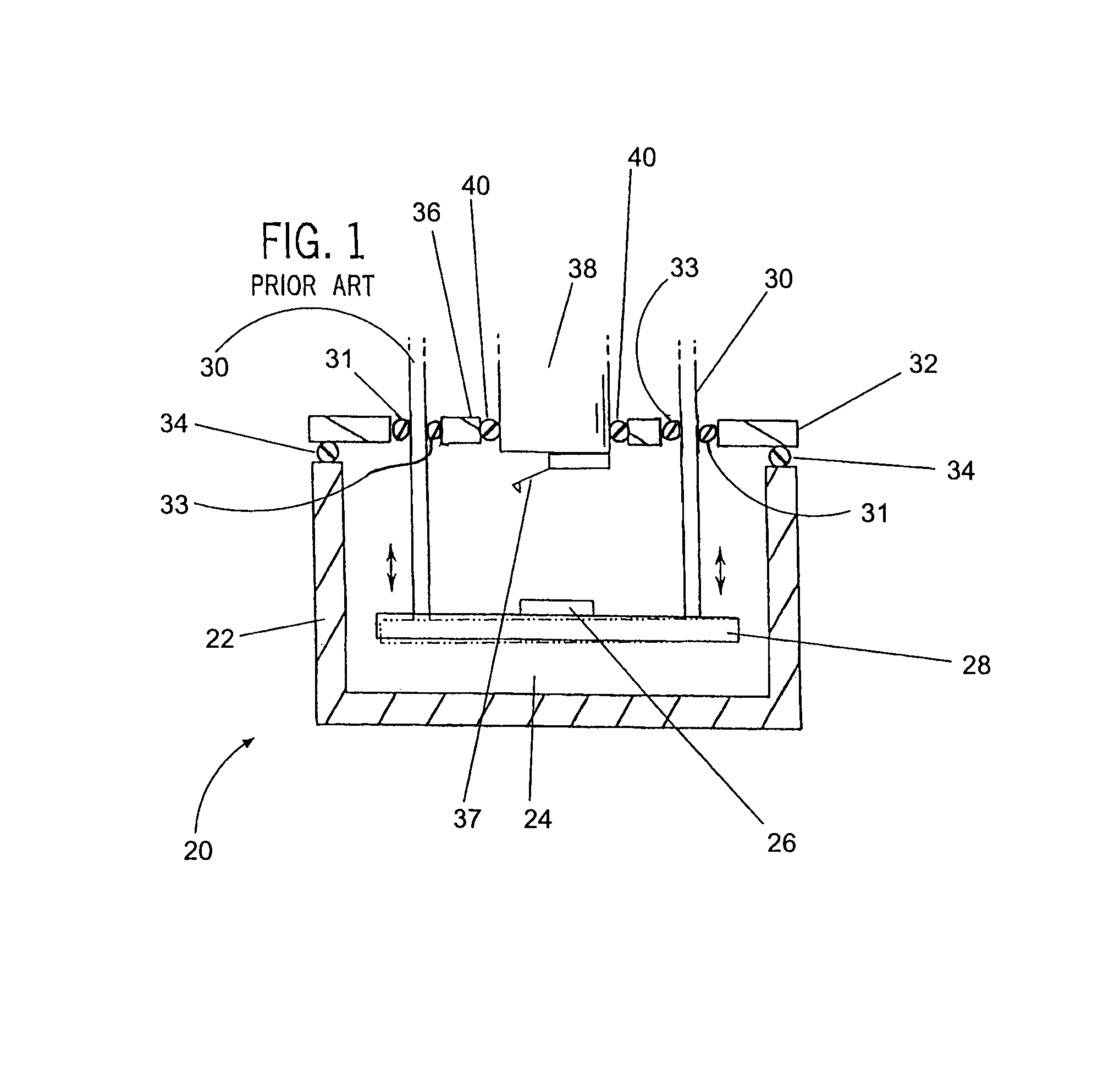
[0043]Turning initially to FIG. 1, an example of a conventional AFM structure 20 for performing environmental AFM measurements is illustrated. The conventional AFM 20 includes a chamber 22 defining an open interior 24 in which a sample 26 can be positioned. The sample 26 is supported on a platform 28 that is vertically movable within the chamber 22 by the actuation of a pair of screws 30 secured to opposite sides of the platform 28. The screws 30 extend upwardly through openings 31 in a cover 32 positioned over the chamber 22 in order to completely enclose the chamber 22. The cover 32 includes a pair of first sealing members 33 disposed within the openings 31 that surround and sealingly engage the screws 30 and a peripheral sealing member 34, such as a rubber gasket. The sealing member 34 is positioned around the periphery of the cover 32 and engages the chamber 22 in order to provide a seal between the chamber 22 and the cover 32 that effectively encloses the interior 24 of the cha...


PUM


Abstract

An apparatus and method of analyzing a sample to be scanned within a hermetically sealed housing of an atomic force microscope (AFM) while the interior of the housing is maintained at one of a number of various environmental conditions. The AFM includes an XYZ stage assembly on which a sample holder supporting the sample may be releasably positioned. The stage assembly allows for the manipulation of the sample and sample holder in the X, Y and Z axes without disturbing any environmental condition present within the chamber due to the hermetic seal maintained between the stage assembly and the AFM during the motion of the stage assembly. The ability of the stage assembly to manipulate the sample in each of the three directions while the sample is enclosed within the AFM also allows the AFM to compensate for non-parallel scanning planes and for drift in all three directions occurring in the sample because of the different environmental conditions in which the sample may be scanned. The scan is performed by the AFM using a scanning tube sealingly disposed within the housing and capable of moving small distances in the X, Y and Z axes. Fine adjustments to the position of the tube in order to accurately scan the sample are accomplished by the inclusion of sectioned piezoelectric elements within the tube which are capable of adjusting the position of a probe or cantilever attached to the end of the tube in small, highly accurate distances in each of the X, Y and Z directions.

Description

BACKGROUND OF THE INVENTION[0001]1. Field of the Invention[0002]The present invention relates to scanning probe microscopes (SPMs) including atomic force microscopes (AFMs) and, particularly, to an AFM that has a hermetically sealed superstructure that allows analyzation of a sample under different environmental conditions.[0003]2. Description of the Related Art[0004]An Atomic Force Microscope (“AFM”), as described for example, in U.S. Pat. No. RE34,489 to Hansma et al. (“Hansma”), is a type of scanning probe microscope (“SPM”). AFMs are high-resolution surface measuring instruments. Two general types of AFMs include contact mode (also known as repulsive mode) AFMs, and cyclical mode AFMs (periodically referred to herein as TappingMode.TM. AFMs). (Note that TappingMode.TM. is a registered trademark of the present assignee.)[0005]The contact mode AFM is described in detail in Hansma. Generally, the contact mode AFM is characterized by a probe having a bendable cantilever and a tip. T...

Claims


Application Information

Patent Timeline
IPC IPC(8): G01N13/16G01B5/28G01Q30/08
CPCB82Y35/00G01Q30/06G01Q30/08
Inventor MARKAKIS, STEPHEN M.LIPPIRE, PETER D.
Owner BRUKER NANO INC
Why Eureka
Try Eureka