Tire measuring device with a modulated backscatter transponder self-sufficient in terms of energy

a technology of backscatter transponder and measuring device, which is applied in vehicle tyre testing, instruments, roads, etc., can solve the problems of battery acid leakage, unsuitable treatment, and inability to meet the needs of users, and achieves the effect of being particularly easy to implement and robus

Inactive Publication Date: 2006-07-18
SIEMENS AG
View PDF14 Cites 10 Cited by
  • Summary
  • Abstract
  • Description
  • Claims
  • Application Information

AI Technical Summary

Benefits of technology

The invention describes a way to make a tire measurement device that works well and is easy to use. It uses layers made from ceramics that have special properties to convert pressure into electricity or control how sensitive they are to changes in electrical fields. This allows for accurate measurements when trying to determine things like the age of a tire's rubber compound.

Problems solved by technology

This patent discusses how important factors like tire pressure, temperature, and friction play a role in ensuring safe driving and good steering control for cars. However, traditional methods of monitoring these things involve expensive and potentially dangerous equipment, while wireless solutions tend to rely on batteries that wear down quickly due to extreme environments. The technical problem addressed by this patent is finding ways to efficiently harness the existing mechanical energy within wheels to power sensors without requiring costly or risky components.

Method used


Image

  • Tire measuring device with a modulated backscatter transponder self-sufficient in terms of energy
  • Tire measuring device with a modulated backscatter transponder self-sufficient in terms of energy
  • Tire measuring device with a modulated backscatter transponder self-sufficient in terms of energy

Examples


Embodiment Construction

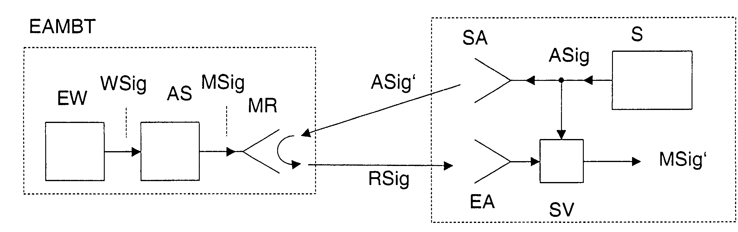
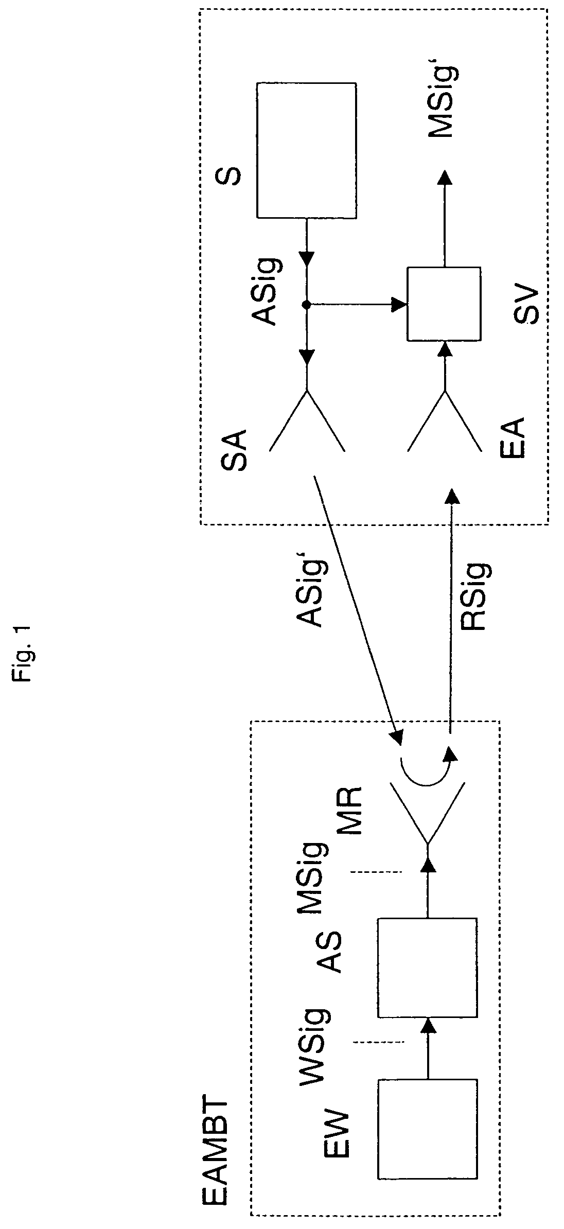
[0045]FIG. 1 shows the basic structure of the modulated backscatter transponder self-sufficient in terms of energy and a remotely-interrogatable radio sensor self-sufficient in terms of energy. The modulated backscatter transponder self-sufficient in terms of energy EAMBT includes at least the following components. The energy converter EW converts the available ambient energy in the form of an energy alternating value to an electrical alternating value or an alternating signal WSig.

[0046]Optionally, this alternating signal is adapted by another interface circuit so that, as resulting modulation signal Msig, it is particularly well suited for modulating the reflector MR that can be modulated. The original alternating value in the form of an alternating signal is in this case thus converted to a derived alternating value in the form of a modulation signal.

[0047]It can be especially useful for this interface circuit to include a transformer. The reflector that can be modulated, for exa...


PUM


Abstract

A tire measuring device has a converter for converting the ambient energy to an alternating value, and a reflector that can be modulated by the alternating value.

Description


Claims


Application Information

Patent Timeline
Owner SIEMENS AG
Why Eureka
Try Eureka