Low voltage power supply for spark igniter and flame sense

a low-voltage power supply and spark igniter technology, applied in the direction of dc-dc conversion, efficient power electronics conversion, lighting and heating apparatus, etc., can solve the problems of parts decrease, production costs are kept down, etc., to reduce power consumption, reduce power consumption, and reduce production costs

Inactive Publication Date: 2011-05-17
ROBERTSHAW CONTROLS CO
View PDF33 Cites 21 Cited by
  • Summary
  • Abstract
  • Description
  • Claims
  • Application Information

AI Technical Summary

Benefits of technology

[0006]In one embodiment of the present invention, the power supply circuit includes only one transformer with a specified resonant frequency to reduce power consumption. With the power consumption reduced, the ability to use low voltage power supplies such as batteries, or self-supplied voltage systems such as a thermopile or a hydro generator, presents itself. In addition, production costs are kept down due to the decrease in parts used to produce the circuits.
[0007]In one specific embodiment, the power supply circuit provides a high-voltage alternating current (AC) supply to flame sense circuit and spark ignition circuit. The flame sense circuit utilizes the property of flame rectification, which occurs when a flame bridges two asymmetrically sized electrodes that are energized by the source of alternating current (AC). In this embodiment, the power supply circuit utilizes the resonant property of an inductor-capacitor circuit. Low voltage from a voltage source, e.g., a battery, is supplied through a filter circuit that includes an inductor and capacitor. The primary coil of a transformer and the capacitor form a resonant circuit, wherein the resonant frequency of the circuit is defined by values of inductance and capacitance. A switching device is controlled by a control circuit which generates, in this embodiment, a PWM switching signal with a frequency set to the resonant frequency of the circuit. Preferably, the duty cycle is low to further reduce a power consumption of the circuit.
[0008]In another embodiment, the control circuit utilizes the high-pass filter of the gate of switching device to protect the switching device in case the control circuit outputs a DC signal or lower frequency switching pulse. This allows the use of a smaller switching device since it will not be in an ON condition for any considerable time with low duty cycle on the gate.

Problems solved by technology

In addition, production costs are kept down due to the decrease in parts used to produce the circuits.

Method used


Image

  • Low voltage power supply for spark igniter and flame sense
  • Low voltage power supply for spark igniter and flame sense

Examples


Embodiment Construction

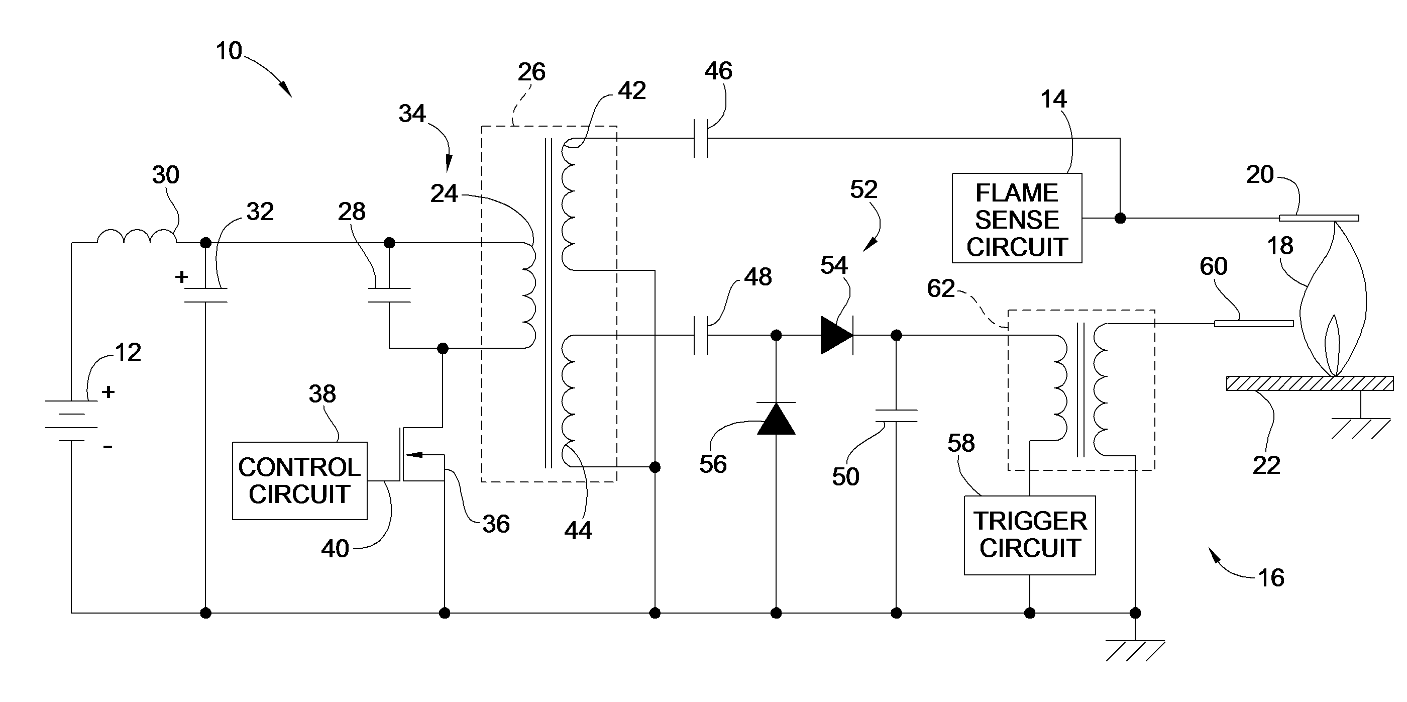
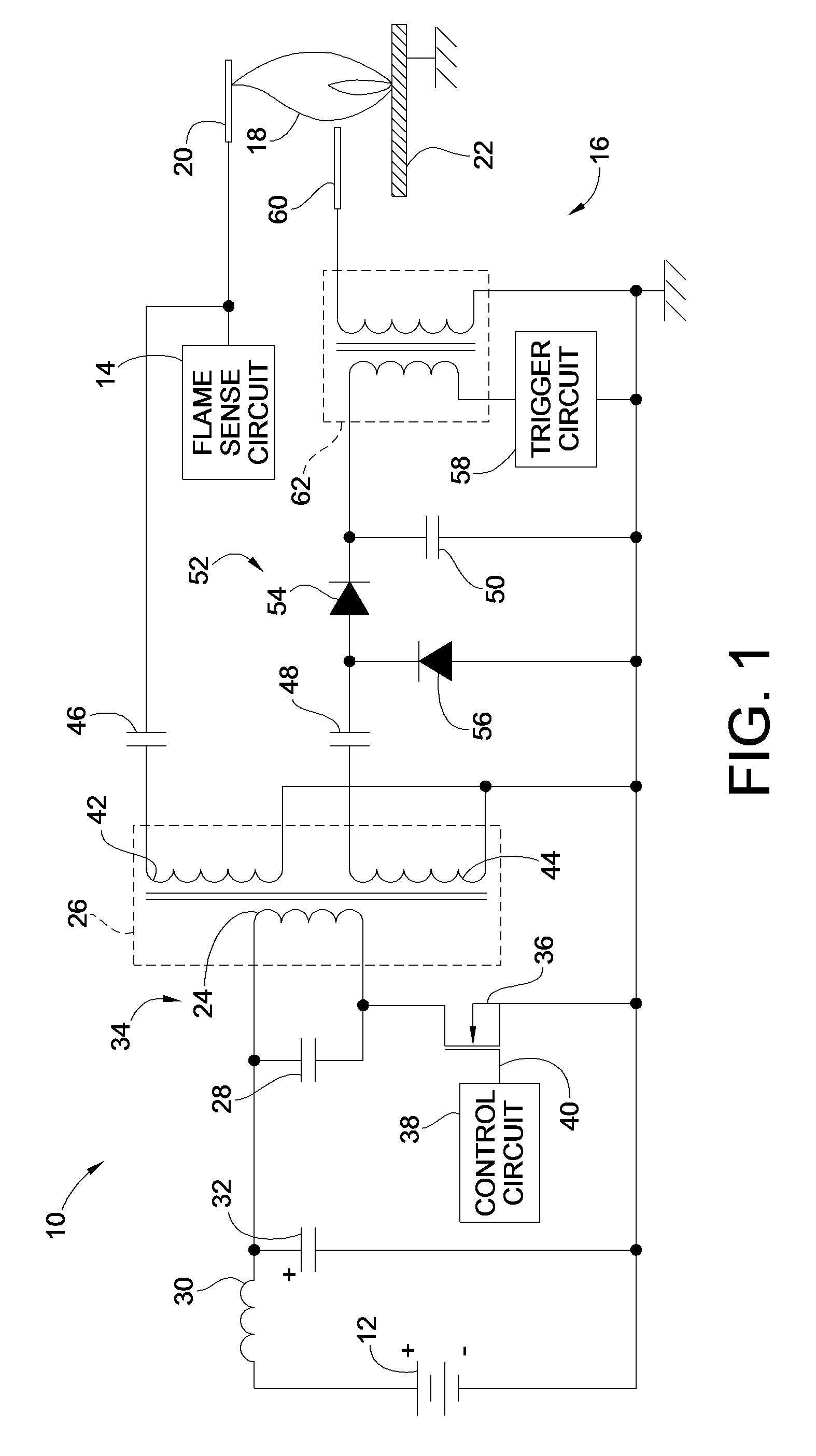
[0013]Turning now to FIG. 1, wherein is illustrated one embodiment of a low voltage power supply circuit 10 for intermittent pilot and / or direct spark ignition systems utilized in gas burning appliances constructed in accordance with the teachings of the present invention. It should be noted at the outset, however, that while the following description will describe features of this embodiment as applied to an operative environment in which it finds particular applicability, such description and embodiment should be taken by way of example only, and not by way of limitation. Other embodiments of the present invention and other operative environments are within the scope of the present invention and their full scope is specifically reserved herein.

[0014]As shown in FIG. 1, the power supply circuit 10 utilizes a low voltage source of electric power, e.g. battery 12, to provide a high-voltage alternating current (AC) supply to flame sense circuit 14 and spark ignition circuit 16. In thi...


PUM


Abstract

A low voltage power supply circuit for intermittent pilot and / or direct spark ignition systems utilized in gas burning appliances is provided. The circuit utilizes a single transformer and a resonant circuit to supply power to both a flame sense circuit as well as the spark generation circuit. The resonant circuit allows the use of low power sources such as batteries or self-supplied voltage systems such as thermopiles or hydro generators. Recognizing that power draw from the low power source is high during a sparking event and recharging of a sparking capacitor, the flame sensing is suspended during the sparking event and for a short recharge time thereafter.

Description

FIELD OF THE INVENTION[0001]This invention generally relates to ignition and flame sense systems for intermittent pilot and direct spark ignition systems for gas burners, and more particularly to power supply circuitry for such intermittent pilot and direct spark ignition systems utilizing low power or self-powered sources.BACKGROUND OF THE INVENTION[0002]Spark ignition systems, such as those used in igniting a pilot flame for gas fired water heaters, space heaters and furnaces are increasingly utilizing intermittent pilot or direct spark ignition systems, which do not use a standing pilot. These intermittent pilots most commonly use a flame sensing circuit to detect the presence of a flame before allowing the opening of the main gas valve that supplies the main burner to avoid unconsumed fuels from flowing freely.[0003]The problem with the state of the art in intermittent pilot and direct spark ignition systems, i.e. systems that do not use a standing pilot flame, is that many of t...

Claims


Application Information

Patent Timeline
Patent Type & Authority Patents(United States)
IPC IPC(8): F23Q3/00
CPCF23Q3/004H02M3/33507Y02B70/1433Y02B70/10
Inventor KAPLAN, YELENA N.RODDA, DALE THOMAS
Owner ROBERTSHAW CONTROLS CO
Why Eureka
Try Eureka