Fiber optic connection for applying axial biasing force to multifiber ferrule

a fiber optic connector and ferrule technology, applied in the field of fiber optic connectors, can solve the problems of dry physical contact across all optical fibers of opposing multifiber connector pairs, and unbalanced biasing force being applied to the rear face of the ferrul

Active Publication Date: 2006-07-18
CORNING OPTICAL COMM LLC
View PDF7 Cites 115 Cited by
  • Summary
  • Abstract
  • Description
  • Claims
  • Application Information

AI Technical Summary

Benefits of technology

[0009]In another advantageous embodiment, a fiber optic connector includes a multifiber ferrule having an end face and an opposed rear face. The end face defines a plurality of optical fiber bores opening therethrough for receiving respective optical fibers and the fiber optic connector defines a longitudinal axis that is generally parallel to each of the optical fiber bores. The fiber optic connector further includes at least one force centering element for applying a biasing force to the ferrule in the direction of the longitudinal axis without generating a moment about a lateral axis defined by the end face of the ferrule. The fiber optic connector further includes a coil spring and a spring seat disposed between the coil spring and the ferrule. The end face of the ferrule defines a first lateral axis generally perpendicular to the longitudinal axis and the rear face defines a convex surface in the direction of the first lateral axis. The end face of the ferrule may further define a second lateral axis generally perpendicular to the longitudinal axis and to the first lateral axis and the rear face may further define a convex surface in the direction of the second lateral axis. Alternatively, the forward portion of the spring seat may define a convex surface in the direction of the first lateral axis and may further define a convex surface in the direction of the second lateral axis.

Problems solved by technology

However, significant advances in geometry control, such as optimal fiber height, array uniformity, optical fiber angle, core dip and ferrule end face angle, have not consistently resulted in dry physical contact across all of the optical fibers of opposing multifiber connector pairs.
Even if the coil spring does not buckle, the geometry and inherent nature of the coil spring makes it likely that an unbalanced biasing force will be applied to the rear face of the ferrule in a direction other than along the longitudinal axis.
As a result, the biasing force will apply an undesired moment to the ferrule in addition to the desired axial force.
Thus, despite the presence of substantially perfect geometry features in mating optical fibers and ferrules, a biasing force that is not applied along the longitudinal axis of a multifiber ferrule, or is not balanced about the longitudinal axis of a multifiber ferrule, will not consistently produce dry physical contact between a mated pair of fiber optic connectors.

Method used


Image

  • Fiber optic connection for applying axial biasing force to multifiber ferrule
  • Fiber optic connection for applying axial biasing force to multifiber ferrule
  • Fiber optic connection for applying axial biasing force to multifiber ferrule

Examples


Embodiment Construction

[0034]The present invention now will be described more fully hereinafter with reference to the accompanying drawings, in which exemplary embodiments of the invention are shown, including the embodiment presently contemplated by the inventors as being the best mode of practicing the claimed invention. The invention may, however, be embodied in many different forms and should not be construed as limited to the embodiments set forth herein. Instead, these embodiments are provided so that this disclosure will be thorough and complete, and will fully convey the scope of the invention to those skilled in the art. Like reference numbers refer to like elements throughout the detailed description and the various drawings.

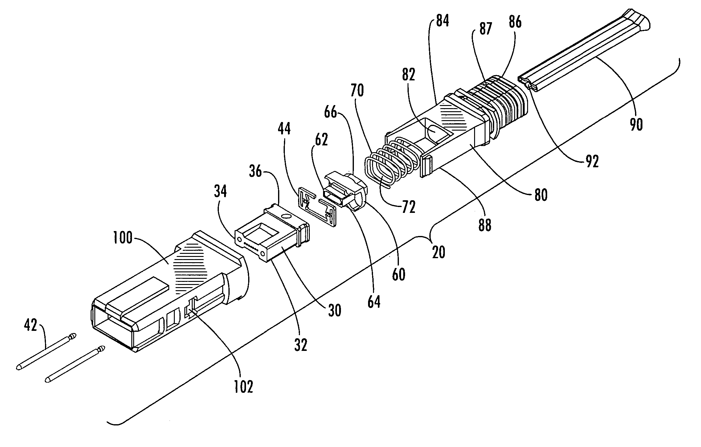
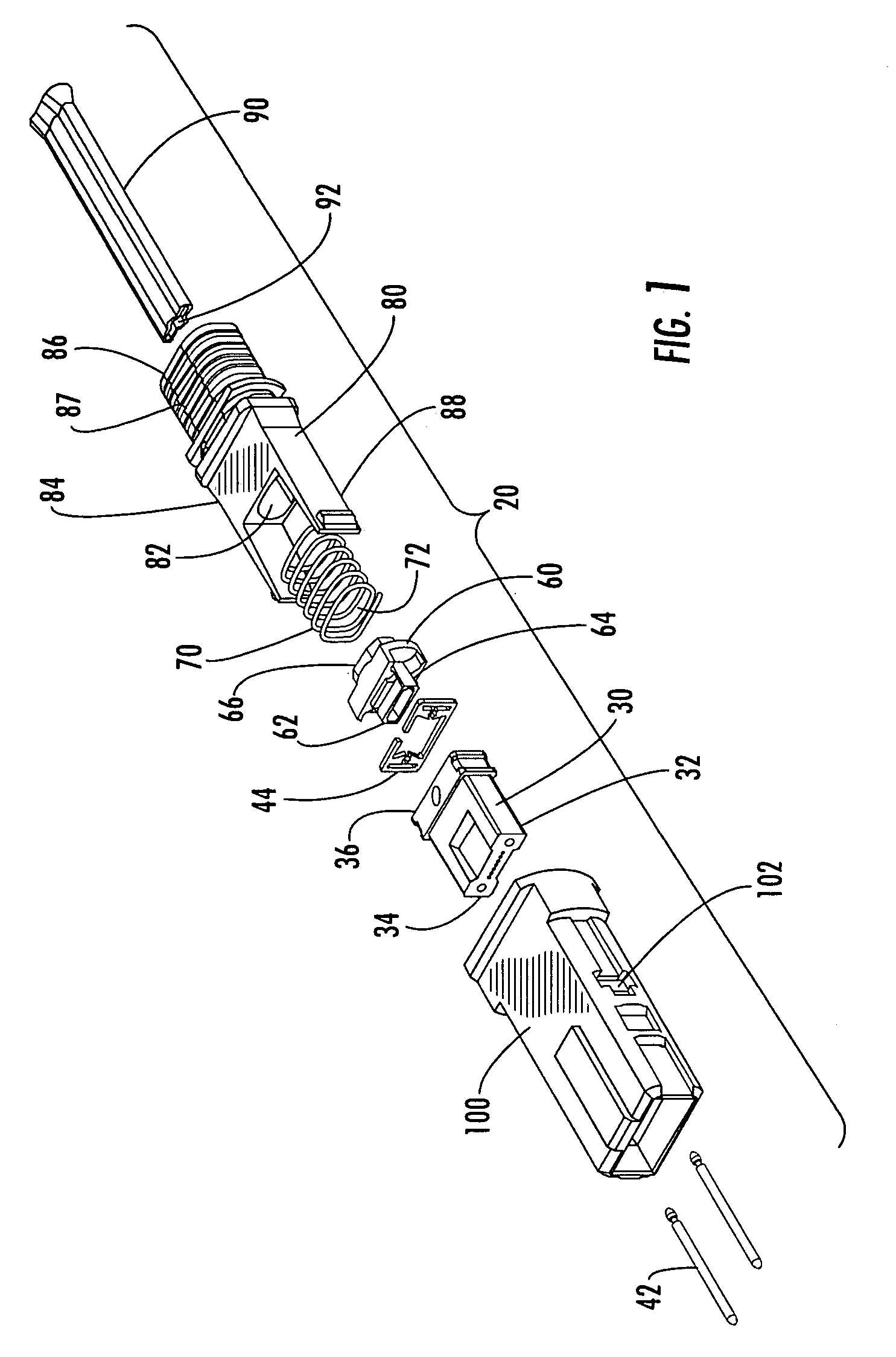
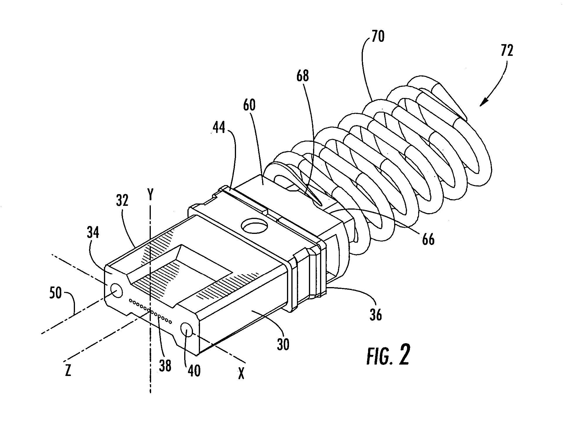
[0035]Referring now to the accompanying drawings, FIGS. 1–4 show a fiber optic connector 20 according to an exemplary embodiment of the present invention. The illustrated embodiment of the connector 20 comprises an MT-type multifiber ferrule 30 having a ferrule body 32 that ...


PUM


Abstract

A fiber optic connector includes a multifiber ferrule and at least one force centering element for applying a biasing force to the ferrule in the longitudinal direction without introducing a moment about a lateral axis. The connector further includes a coil spring for exerting the biasing force and a spring seat disposed between the coil spring and the ferrule. The rearward portion or the forward portion of the spring seat may be provided with a pair of outwardly extending protrusions that are laterally spaced apart to transfer the biasing force to the ferrule. Alternatively, the forward portion of the spring seat or the rear face of the ferrule may define a convex surface. Alternatively, the ferrule defines a convex surface in the direction of a first lateral axis and the spring seat defines a convex surface in the direction of a second lateral axis perpendicular to the first lateral axis.

Description

BACKGROUND OF THE INVENTION[0001]The present invention relates generally to fiber optic connectors, and more particularly, to a fiber optic connector including a multifiber ferrule and means for applying an axial biasing force to the ferrule.[0002]The proliferation of optical communications and data transfer has dramatically increased the use of fiber optic connectors including multifiber ferrules for simultaneously interconnecting a plurality of optical fibers. Not only are multifiber connectors being utilized in greater numbers, but increased performance demands are being placed upon the optical connections between mated connectors. As a result, there is an increased demand in optical communications for what has become generally known as “low-loss, intermateable, multifiber connectors.” For example, in order to maximize signal transmission between pairs of opposed optical fibers, multifiber connectors are required to align each of the optical fibers very precisely, especially for ...

Claims


Application Information

Patent Timeline
Patent Type & Authority Patents(United States)
IPC IPC(8): G02B6/38
CPCG02B6/3821G02B6/3885
Inventor LUTHER, JAMES P.COOKE, TERRY L.DEJONG, MICHAELELKINS, II, ROBERT B.NIELSEN, LARS K.THEUERKORN, THOMASKLAVUHN, TORY A.
Owner CORNING OPTICAL COMM LLC
Why Eureka
Try Eureka