Contact material, composite sintered component and method of producing same

a technology of contact components and composite sintered parts, which is applied in the direction of metal layered products, electrical appliances, basic electric elements, etc., can solve the problems of unsatisfactory abnormal noises, lubricating film forming conditions for contact components that slide under high surface pressure at extremely slow speeds, and the inability to ensure the prevention of abnormal noises, improve seizure resistance, and improve the effect of seizure resistan

Inactive Publication Date: 2006-07-18
KOMATSU LTD
View PDF14 Cites 9 Cited by
  • Summary
  • Abstract
  • Description
  • Claims
  • Application Information

AI Technical Summary

Benefits of technology

[0019]Examples of Fe—Al base alloys and Fe—Si base alloys having an ordered phase are Fe3Al, FeAl, Fe3Si, and FeSi. It is well known that each of these crystals has a BCC structure in which Fe atoms, Al atoms and / or Si atoms extremely strongly attract one another such that they are regularly arranged in the closest proximity to one another, and therefore, the hardness of the ordered phase becomes similar to that of intermetallic compounds as the degree of order increases. In addition, since the phase separation into two kinds of ordered phases, that is, the phase separation into Fe—Al and Ni—Al or Co—Al is involved in Fe—Al base alloys to which Ni and Co have been added, the alloys can be significantly hardened by applying aging treatment at e.g., 600° C. or by slowing the cooling speed down after sintering. This is very useful for imparting wear resistance. However, the Vickers hardness of these ordered phases does not exceed Hv 800 and if these alloys are used as contact material, there is such a merit that the aforesaid implement pin (i.e., corresponding mating contact member) is not attacked by the bushing formed from the contact material and the contact component itself exhibits excellent wear resistance, because the surface of the implement pin has been hardened by thermal treatment.
[0050]The twenty-first and twenty-second aspects may be arranged such that the backing is provided with a collar and a wear-resistant material or the sintered contact material is integrated with the sliding contact surface of the collar by one means selected from brazing, sinter-bonding and infiltration, simultaneously with the integration of the backing (a twenty-fourth aspect of the invention). This contributes to a reduction in the production cost.

Problems solved by technology

Since the lubricating conditions, in which such implements for construction machines are used under high surface pressure, are particularly harsh, unpleasant abnormal noises occur when the implements are in service.
Lubricating film forming conditions for contact components that slide under high surface pressure at extremely slow speeds like bushings used for the implements of working machines are extremely severe.
The above steel bushings are hard enough to withstand high load, but present the serious drawback that they are susceptible to seizure and unpleasant abnormal noises so that control is needed to prevent seizure and noises by shortening greasing time intervals.
However, they suffer from the problem that when they are used under extremely slow and high load conditions such as encountered by implements, lubricant starvation tends to occur and as a result, satisfactorily improved seizure resistance and prevention of abnormal noises cannot be ensured.
The contact components made from the sintered contact materials, which are provided with pores impregnated with a large amount of lubricant for improving the lubricating condition during sliding, have also failed in improving seizure resistance and prevention of abnormal noises as much as expected, because the lubricating condition gets all the worse for the provision of a number of pores within the sintered body.
Where a bronze base material (e.g., Cu—Sn and Cu—Pb), which is a material composed of dissimilar constituents, is used with the intention of increasing resistance to seizure caused between an implement steel pin and an implement bushing, the material becomes fatigued under high surface pressure and tends to wear away very soon because of the severe lubricating condition.
However, lubricant starvation easily occurs as pointed out earlier so that satisfactory improvements in seizure resistance and protection against abnormal noises cannot be expected.
In cases where graphite having high self-lubricity is embedded in a cast high-strength brass bushing and the graphite is impregnated with a lubricating oil for achieving increased greasing ability and prolonged greasing intervals, the area percentage of the holes to be filled with graphite is normally limited to 25 to 30%, so that the area over which the lubricant is spread decreases as the sliding distance decreases, resulting in occurrence of local seizure and a failure to ensure satisfactory self-lubricity for a long time.
In addition, the processes of machining to make the holes for graphite and filling the holes with graphite lead to a considerable increase in the cost.
Further, the technique such as disclosed in Japanese Patent Publication No. 5-156388, in which graphite is added as a solid lubricant to a high-strength aluminum bronze sintered material in a large amount of 3 to 8 wt % (about 12 to 36% by volume) in order to ensure improved seizure resistance, has not proved successful in that brittleness due to the large graphite content leads to poor sliding properties under high surface pressure and insufficient wear resistance.
Metallic sintered bodies containing large amounts of solid lubricant are difficult to be sintered and therefore require pressurization treatment during sintering to achieve practical strength.
For instance, in the case of the above-described double-layered sintered contact component formed by integrally bonding an Al bronze base sintered contact material containing 3 to 8 wt % graphite to a backing with a phosphor bronze material therebetween, pressurization treatment is needed in the sintering process and at least the integration process inevitably causes an increase in the cost.

Method used


Image

  • Contact material, composite sintered component and method of producing same
  • Contact material, composite sintered component and method of producing same
  • Contact material, composite sintered component and method of producing same

Examples


example 1

[0079]Various alloys having different compositions were prepared using electrolytic iron (99.95 wt %), Al and Co. These alloys were melted, produced and forged under a vacuum atmosphere and then cut into small pieces, forming specimens. The relationship between the magnetic transition temperature (Curie point (° C.)) and hardness of each alloy and thermal treatment was checked.

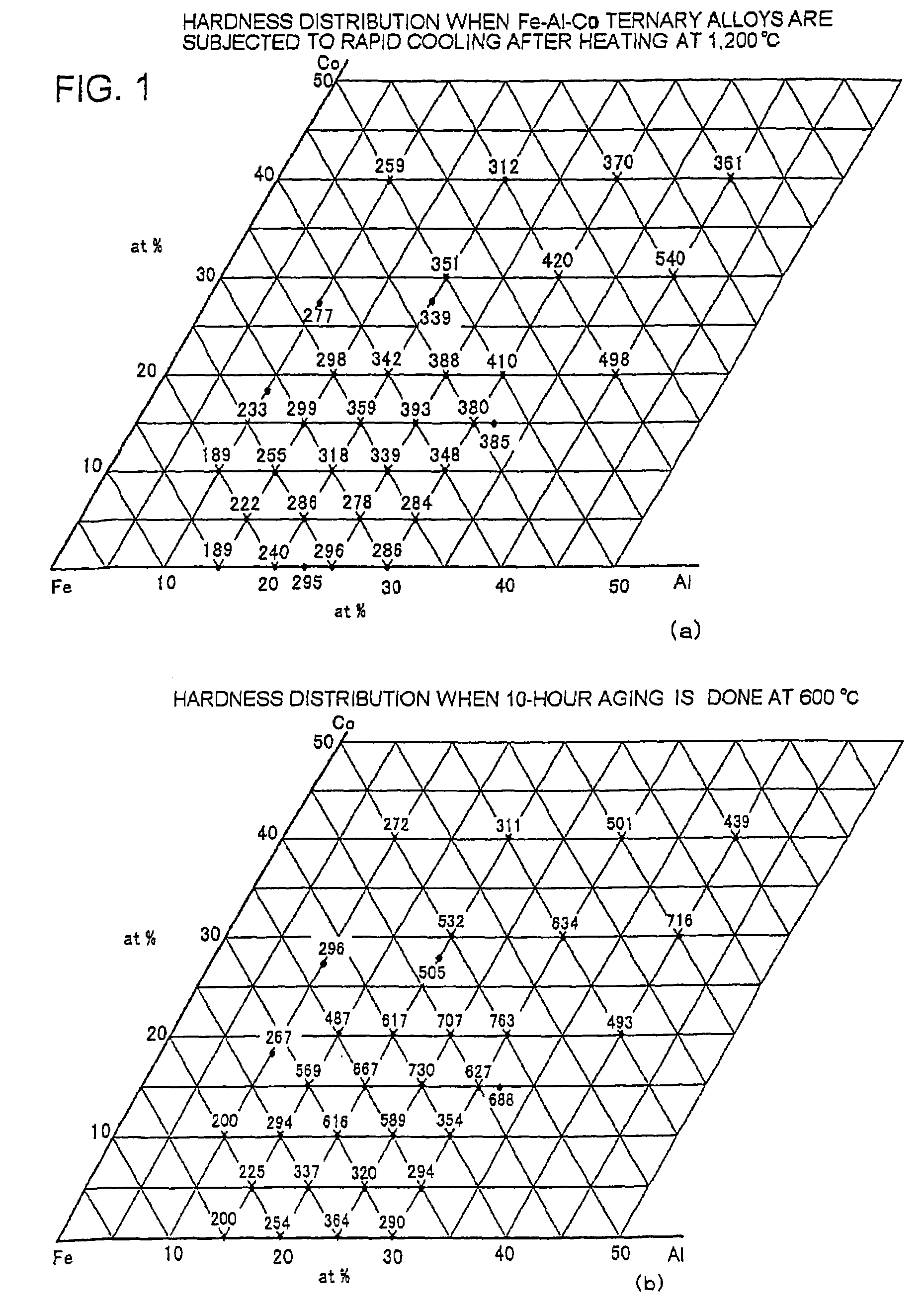
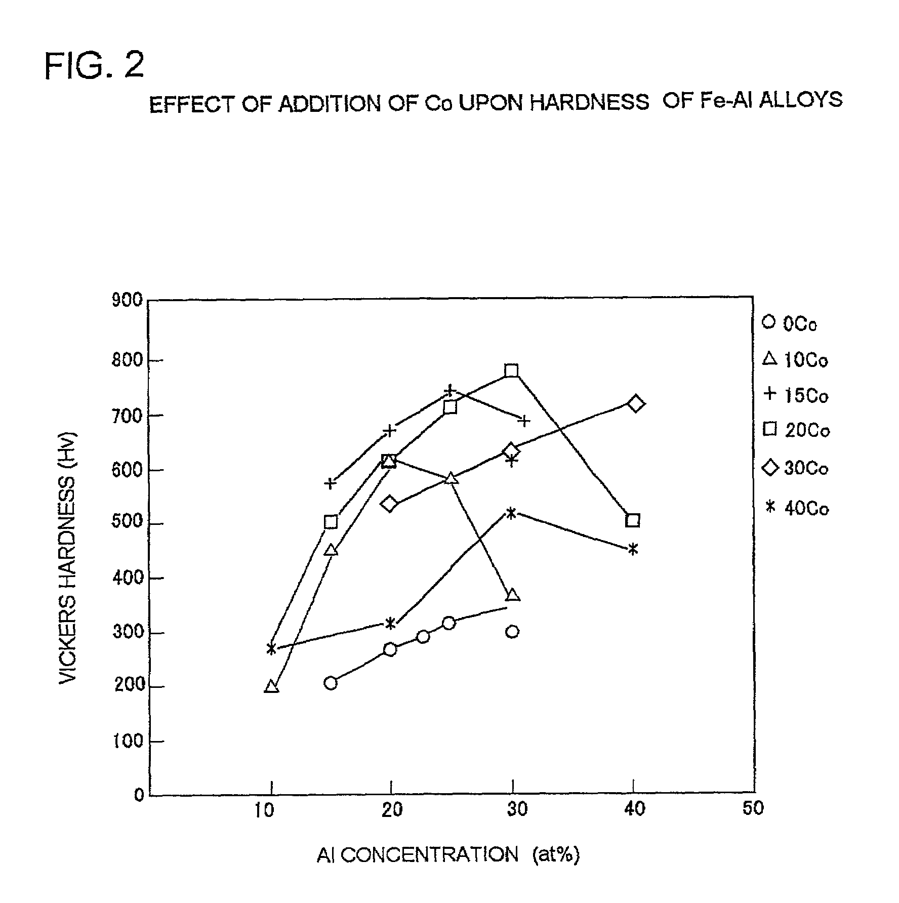
[0080]FIG. 1(a) shows the Vickers hardness distribution of Fe—Al—Co ternary alloys which contain 0 to 40% by atom Co and 0 to 40% by atom Al and were rapidly cooled after heating at 1,200° C. FIG. 1(b) shows the Vickers hardness distribution of these alloys which were further subjected to aging treatment at 600° C. for 10 hours after the rapid cooling. It is understood from these figures that while a slight tendency for hardening is found in the rapidly cooled alloys (shown in FIG. 1(a)) containing 25 to 40% by atom Al and 15 to 30% by atom Co, a significantly hardened zone exists in the alloys which underwent...

example 2

[0084]Evaluations of the wear resistance of Fe ordered phases were conducted in the following procedure: Cylindrical specimens having a diameter of 10 mm and length of 50 mm were prepared from ingot materials of the compositions as shown in TABLE 1. After the hardness of these specimens had been adjusted by controlling the time required for age hardening at 500° C. and 600° C., the specimens of the contact materials were respectively pressed against a Portland cement disk containing 20 wt % SiC under an oil-lubricated condition. Then, the wear resistance of each material to sediment was evaluated.

[0085]

TABLE 1Fe BASE ORDERED PHASE ALLOY INGOT MATERIALS (wt %)NoFeAlCoNiMnSiHARDNESS (Hv)1Bal.123002Bal.12207153Bal.12206704Bal.12105405Bal.103325

[0086]FIG. 4 shows a conceptual view of a tester and test conditions. In this test, a S45 comparative material which had undergone quenching and tempering so as to have a Vickers hardness of 500 was mounted on the tester together with the specime...

example 3

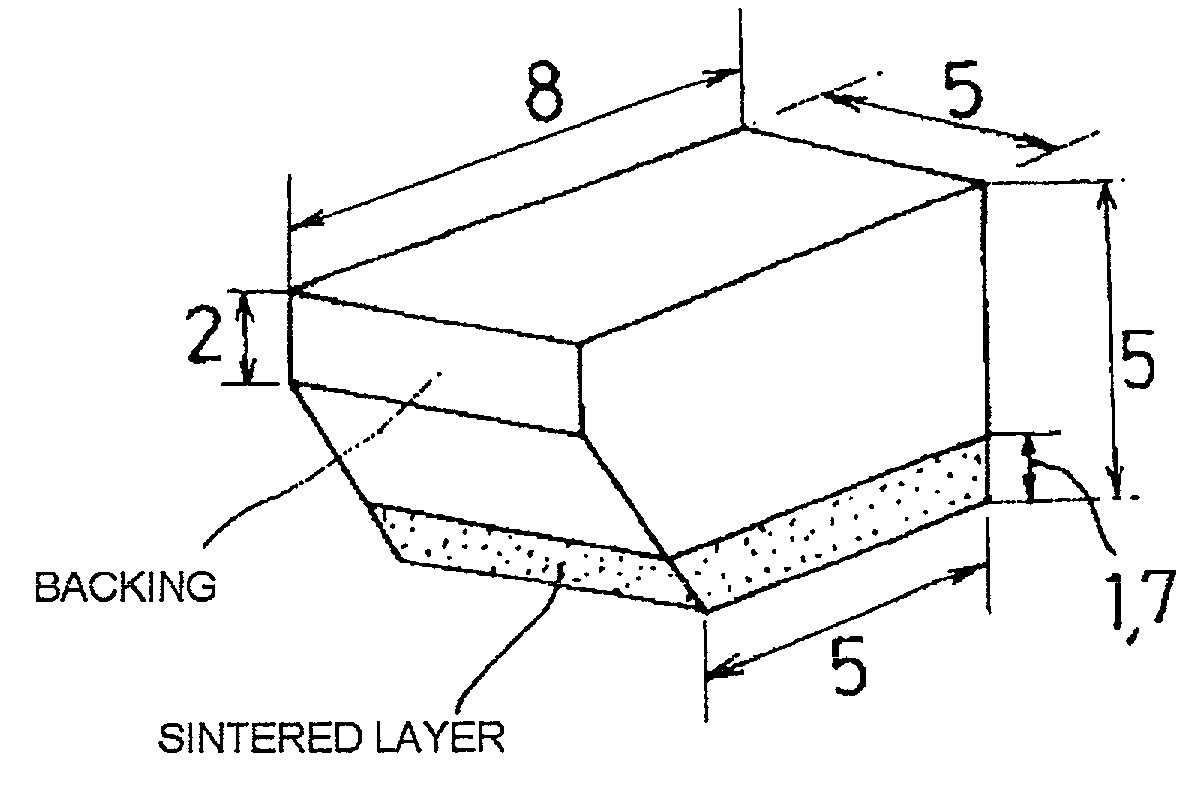
[0087]In this example, each of the alloys shown in TABLE 2 was melted in vacuum and then formed into a sheet-like shape by hot forging and hot rolling at 1,000 to 1,150° C. This sheet-like material was cut and rounded, thereby obtaining a bushing machined into the shape shown in FIG. 6. The bushings thus prepared were used as sliding test specimens and adjusted so as to have different hardnesses by controlling the processing time taken for aging at 600° C. Used as comparative examples were a carburized bushing (Comparative Example 1) formed from SCM420 case hardening steel and having a surface carbon concentration of about 0.8 wt %; an S43C quenched, tempered bushing (Comparative Example 2); and a high-strength brass quarternary material (Cu, 25 wt % Zn, 5 wt % Al, 3 wt % Mn, 2.5 wt % Fe) (Comparative Example 3).

[0088]

TABLE 2COMPOSITION OF Fe BASE ORDERED PHASE ALLOYSFOR SLIDING TESTS (wt %)HARDNESSHARDNESSAFTER RAPIDAFTER AGINGNoFeAlCuCoNiSiCOOLING (Hv)(Hv) 6Bal. 5170175 7Bal.12295...


PUM

PropertyMeasurementUnit
magnetic transition temperatureaaaaaaaaaa
temperatureaaaaaaaaaa

Abstract

A contact material which provides improved wear resistance as well as reduced adhesion utilizing the features of an intermetallic compound having an ordered phase, with the intention of (i) improving the seizure resistance and / or wear resistance of an implement bearing which slides under low-speed, high-surface-pressure conditions and is susceptible to lubricant starvation; (ii) preventing abnormal noises; and (iii) achieving prolonged greasing intervals. The contact material contains 10% by volume or more a metallic alloy phase having such a composition range that causes an order-disorder transition. The metallic alloy phase is a Fe base alloy phase containing one or more elements selected from the group consisting of Al, Si, Co and Ni.

Description

TECHNICAL FIELD[0001]The present invention relates to a contact material, composite sintered contact component and producing method thereof, which are intended for an improvement in the seizure resistance and / or wear resistance of bearings subject to high surface pressure and for prevention of abnormal noise and extension of greasing intervals in such bearings.BACKGROUND OF THE INVENTION[0002]As bearings subject to higher surface pressure and lower speed conditions (such as bushings for implements mounted on construction machines), steel bushings, which have been carburized or induction-hardened to attain wear resistance as an important feature, are presently used in grease-lubricated situations. Since the lubricating conditions, in which such implements for construction machines are used under high surface pressure, are particularly harsh, unpleasant abnormal noises occur when the implements are in service. As measures for avoiding noises, a lubricating film is applied to the slidi...

Claims


Application Information

Patent Timeline
Patent Type & Authority Patents(United States)
IPC IPC(8): F16C17/12B32B15/01B32B15/18B32B15/20F16C17/24B22F7/00F16C33/12B22F7/04C22C1/08C22C33/02C22C38/00C22C38/06C22C38/10
CPCB22F7/004B22F2998/10Y10T428/12Y10T428/12951Y10T428/12917Y10T428/12063Y10S384/912Y10T428/12479B22F3/10B22F3/18C22C38/06
Inventor TAKAYAMA, TAKEMORITANAKA, YOSHIKIYOONISHI, TETSUO
Owner KOMATSU LTD
Why Eureka
Try Eureka