Eureka AIR delivers breakthrough ideas for toughest innovation challenges, trusted by R&D personnel around the world.

Vehicle energy storage system control methods and method for determining battery cycle life projection for heavy duty hybrid vehicle applications

a technology of hybrid electric vehicles and energy storage systems, which is applied in the direction of battery/fuel cell control arrangements, electric devices, capacitors, etc., can solve the problems of premature degradation of ess and generally not a good indication of the performance of electric vehicles or hybrid electric vehicles, and achieve the effect of reducing the operating range of energy storage banks and modifying capacity

Active Publication Date: 2006-07-18
GENERAL ELECTRIC CO
View PDF25 Cites 101 Cited by
  • Summary
  • Abstract
  • Description
  • Claims
  • Application Information

AI Technical Summary

Problems solved by technology

However, as between one or more individual energy storage banks, there may be a variation in the SOC that, utilizing conventional ESS power commands, could result in premature degradation of the ESS.
While this approach is useful in comparing one battery to another battery, it is generally not a good indication of the performance in an electric vehicle or hybrid electric vehicle, since the voltage where maximum power is transferred is 50% of the open circuit voltage.

Method used


Image

  • Vehicle energy storage system control methods and method for determining battery cycle life projection for heavy duty hybrid vehicle applications
  • Vehicle energy storage system control methods and method for determining battery cycle life projection for heavy duty hybrid vehicle applications
  • Vehicle energy storage system control methods and method for determining battery cycle life projection for heavy duty hybrid vehicle applications

Examples


Embodiment Construction

[0027]Disclosed herein is a method and system for extending the life and performance of hybrid and electric vehicle energy storage systems (ESS) by utilizing (among other aspects) customized energy charging, discharging and redistribution techniques that depend upon, among other aspects: state of charge (SOC) reset calculations, thermal models of the ESS, variations in energy storage technology within an ESS, energy storage end-of-life status, and variations in life cycle between individual storage banks.

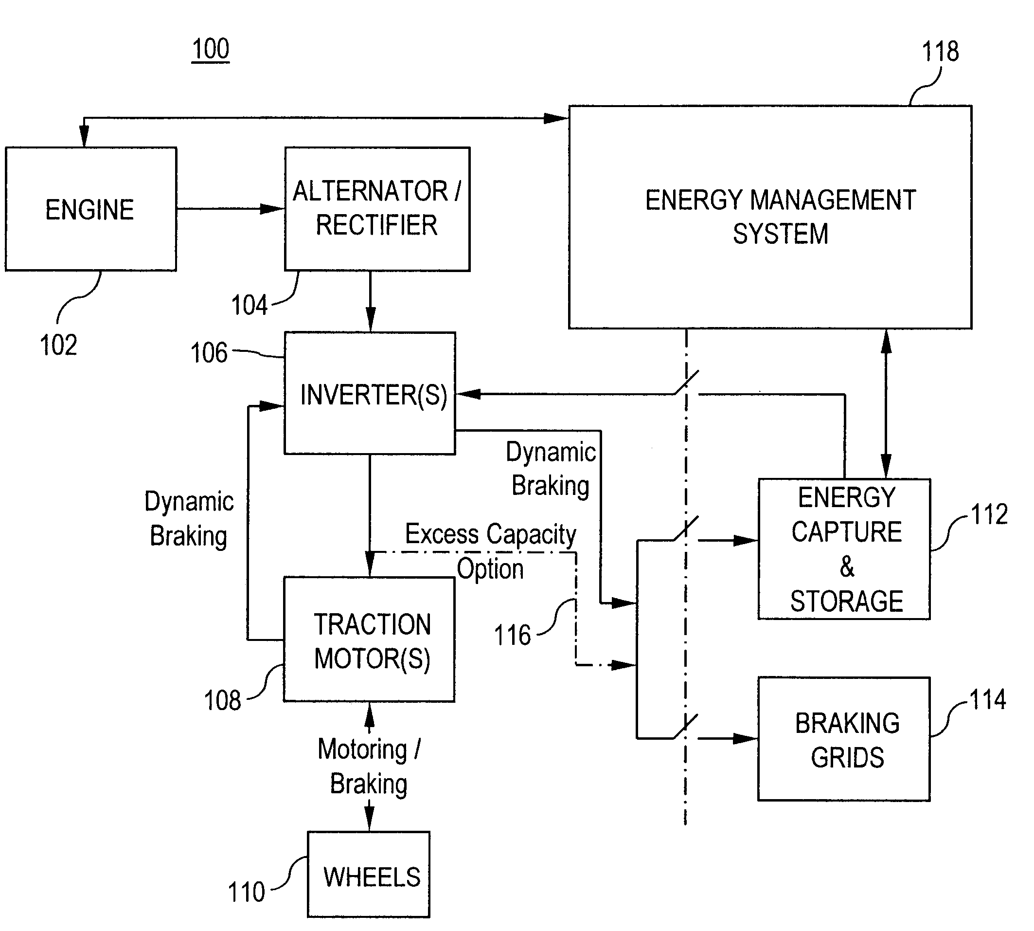
[0028]Referring initially to FIG. 1, there is shown a system-level block diagram of an exemplary energy generation and storage system 100 for hybrid locomotives or off-highway (OHV) vehicles (or any electric drive vehicle with an associated storage medium), suitable for use in accordance with an embodiment of the invention. Such OHVs may include, for example, large excavators, excavation dump trucks, and the like. By way of further example, such large excavation dump trucks may util...


PUM


Abstract

A method for equalizing a storage parameter for a vehicle energy storage system having one or more energy storage banks associated therewith includes identifying a quiescent period of operation for the vehicle, and determining whether the value of a defined storage quantity for a first energy storage bank differs from the value of the defined storage quantity for a second energy storage bank by a threshold amount. During the quiescent period of operation, one of the first and second energy storage banks is discharged and the other of the first and second energy storage banks is charged. The one of the first and second energy storage banks corresponds to the bank having the value of the defined storage quantity exceeding the value of the defined storage quantity of the other of the first and second energy storage banks.

Description

BACKGROUND OF THE INVENTION[0001]The present disclosure relates generally to vehicle energy storage systems and, more particularly, to vehicle storage system control methods and a method for characterizing traction battery energy and power performance and project remaining service cycle life for heavy-duty hybrid electric vehicle applications.[0002]In electric vehicles and hybrid electric vehicles (e.g., locomotives, off-highway mining vehicles, buses and automobiles), it is necessary to control the operation of the energy storage system in order to obtain high mission performance in terms of average mission speed, range, and / or payload capability, as well as to maximize the operating life of the energy storage system (ESS) and to avoid prematurely degrading thereof. For hybrid vehicles, it is also desirable to maximize the benefits of fuel and / or emissions savings. Existing energy storage systems in such vehicles may include one or more types of batteries, ultra-capacitors and / or f...

Claims


Application Information

Patent Timeline
Patent Type & Authority Patents(United States)
IPC IPC(8): H02J7/00B60L50/15
CPCH02J7/0014B60L3/12B60L7/22B60L11/005B60L11/16B60L11/1857B60L11/1859B60L11/1861B60L11/1868B60L11/1874B60L2200/26B60L2240/545B60L2240/547B60L2240/549Y02T10/7044Y02T10/7005Y02T10/7022Y02T10/7066Y02T10/7055B60L50/40B60L50/30B60L58/16B60L58/14B60L58/20B60L58/26B60L58/15Y02T10/70
Inventor SALASOO, LEMBITKING, ROBERT DEANKUMAR, AJITH KUTTANNAIRSONG, DONGWOOYOUNG, HENRY TODDRICHTER, TIMOTHY GERARDBHUGRA, PRAHLAD
Owner GENERAL ELECTRIC CO
Why Eureka
Eureka Blog
Learn More