Heat sink clip assembly with cammed clip handles

a technology of heat sink and clip handle, which is applied in the direction of cooling/ventilation/heating modification, semiconductor/solid-state device details, semiconductor devices, etc., can solve the problems of large amount of heat produced, difficult clip handling, and complicating packaging, transportation and subsequent assembly processes, etc., to achieve the effect of ensuring the heat sink onto a central processing uni

Inactive Publication Date: 2006-07-18
HON HAI PRECISION IND CO LTD
View PDF10 Cites 11 Cited by
  • Summary
  • Abstract
  • Description
  • Claims
  • Application Information

AI Technical Summary

Benefits of technology

[0008]Accordingly, an object of the present invention is to provide a heat sink cl

Problems solved by technology

During operation of many contemporary electronic devices, large amounts of heat are produced.
However, the clips are usually hard, and extra tools are often needed to manipulate the clips so tha

Method used


Image

  • Heat sink clip assembly with cammed clip handles
  • Heat sink clip assembly with cammed clip handles
  • Heat sink clip assembly with cammed clip handles

Examples


Embodiment Construction

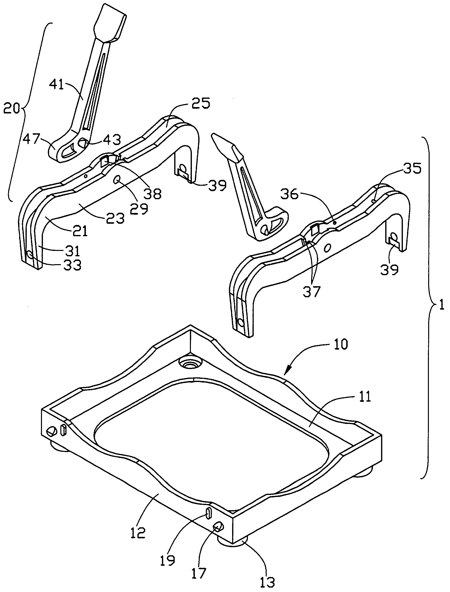
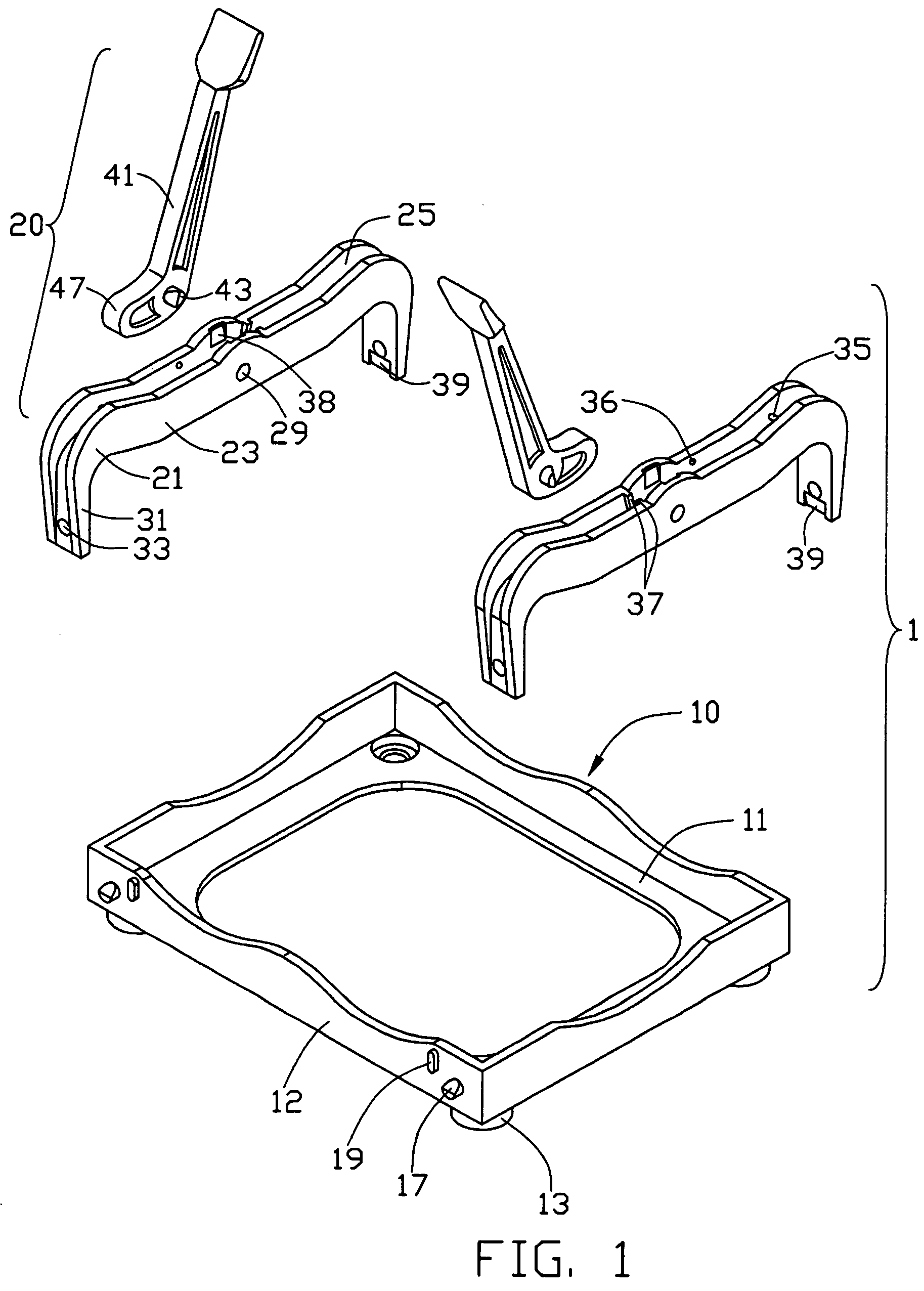
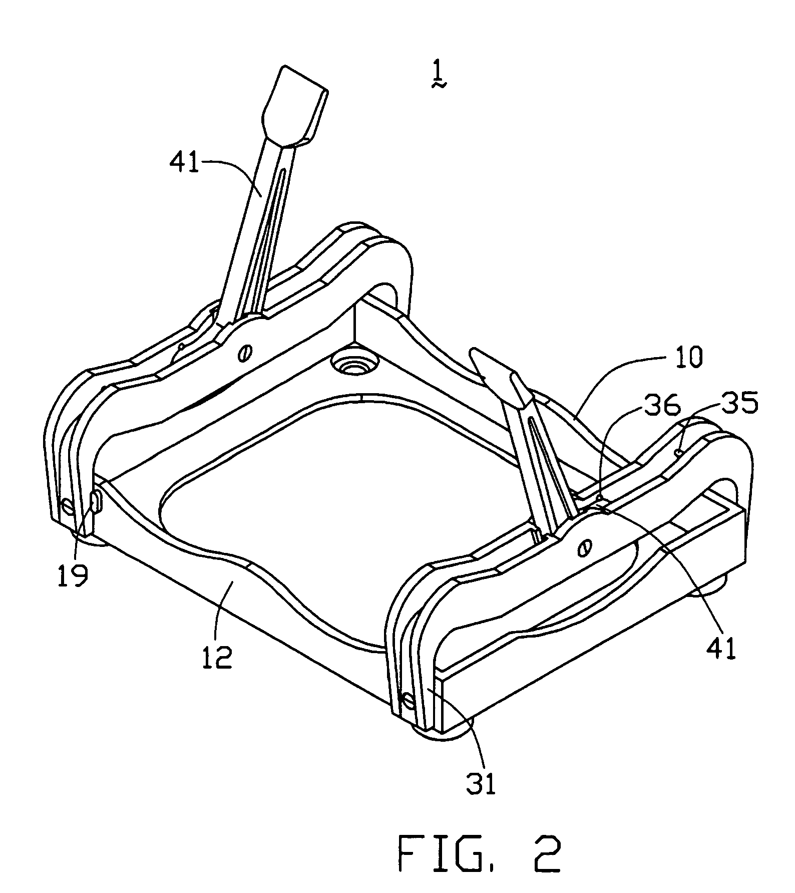
[0016]Referring to FIGS. 1–4, a heat sink clip assembly 1 in accordance with the preferred embodiment of the present invention is used to attach a heat sink 5 to a CPU 7 that is mounted to a PCB 9. The heat sink clip assembly 1 comprises a retention frame or rack 10, and a pair of clips 20.

[0017]The retention frame 10 has a rectangular base 11, and four side plates 12 extending perpendicularly from the base 11. A central opening is defined in the base 11 for accommodating the CPU 7 therein. Four standoffs 13 depend from four corners of the base 11, respectively. A pair of pivots 17 is formed at opposite ends of each of two opposite of the side plates 12. A pair of stops 19 is formed on each of said two opposite of the side plates 12. The stops 19 are between the corresponding pivots 17 and adjacent said pivots 17 respectively.

[0018]Each clip 20 comprises a main body 21, and a cammed handle 41 pivotally attached to the main body 21. The main body 21 comprises a cross beam 23, and two...


PUM


Abstract

A heat sink clip assembly (1) for attaching a heat sink (5) on a CPU (7) includes a retention frame (10), and a pair of clips (20) pivotally attached to two sides of the retention frame. Each clip includes a main body (21), and a handle (41) pivotally attached to the main body. The main body includes a cross beam (23), and two locking arms (31) respectively depending from opposite ends of the cross beam. Each locking arm defines a locking hole (33) at a distal end. The handle has a cam portion (47) at one end thereof. The clips are pivoted outwardly to make way for the heat sink to seat on the CPU. Then the clips are pivoted upwardly, so that the cross beam is suspended above the heat sink. The handle is pivoted downwardly so that the cam portion presses the heat sink to the CPU.

Description

BACKGROUND OF THE INVENTION[0001]1. Field of the Invention[0002]The present invention relates to a heat sink clip assembly, and more specifically to a heat sink clip assembly which readily secures a heat sink onto an electronic package.[0003]2. Related Art[0004]Developments in today's highly information-intensive society have led to remarkable improvements in performances of electronic devices. During operation of many contemporary electronic devices, large amounts of heat are produced. Heat sinks are often attached to the electronic devices to remove heat therefrom.[0005]Various clips are used to attach heat sinks onto the electronic devices. A conventional heat sink clip assembly as disclosed in U.S. Pat. No. 6,205,026, includes a pair of retention modules and a pair of clips. Each clip includes a curved pressing portion, and two legs depending from the pressing portion. A locking hole is defined in each leg. Each retention module is U-shaped. The retention modules are mounted on ...

Claims


Application Information

Patent Timeline
IPC IPC(8): H05K7/18H01L23/40
CPCH01L23/4093H01L2924/0002H01L2924/00
Inventor LEE, HSIEH KUNLEE, DONGYUNZHANG, ZHIJIE
Owner HON HAI PRECISION IND CO LTD
Why Eureka
Try Eureka